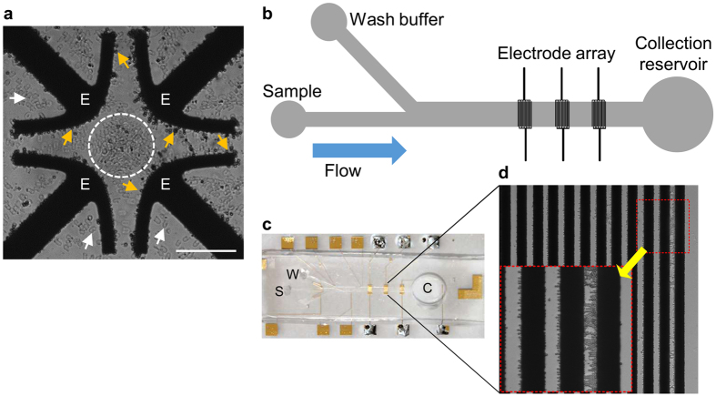
Figure 3.
DEP trapping and characterization of polar capsules. (a) Light microscope image of a mixture of capsules and valves within a quadrupole electrode array chip, used for DEP characterization, at 10Vpp and 2 MHz. Note that the capsules (yellow arrows) are trapped (i.e. pDEP) on the edge of the electrodes (E), whereas valves (white dashed circle and white arrowheads) are repelled (i.e. nDEP) from the electrodes. Scale bar = 100 μm. (b) Schematic description of the DEP-based microfluidic chip, which consists of a main channel with embedded electrode arrays. (c) A photo of the DEP-based chip, showing the sample loading (S), wash buffer (W) channels, and the collection reservoir (C). (d) Magnified view of the electrode array with trapped polar capsules. Inset (red box) shows magnified electrode and capsules. The entire separation process is shown in Supplementary Video 1.

