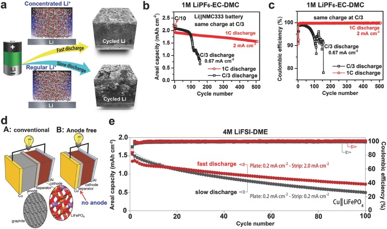
Figure 7.

(a) Schematic illustrations of discharge C rate effect on the interfacial stability of Li metal anode. (b) Cycling stability and (c) CE of Li||NMC cells using 1 m LiPF6/EC‐DMC electrolyte during cycling at different discharge rages (same charge rate C/3). Reproduced with permission.43 (d) Schematic illustrations of battery configurations. A: Conventional LIB (Cu|C6||LiFePO4|Al). B: Anode‐free battery (Cu||LiFePO4|Al). (e) Capacity and CE of anode‐free Cu||LiFePO4 cells using 4 m LiFSI/DME charged at 0.2 mA cm−2 and discharged at either 0.2 or 2.0 mA cm−2. Reproduced with permission.44
