Figure 3.
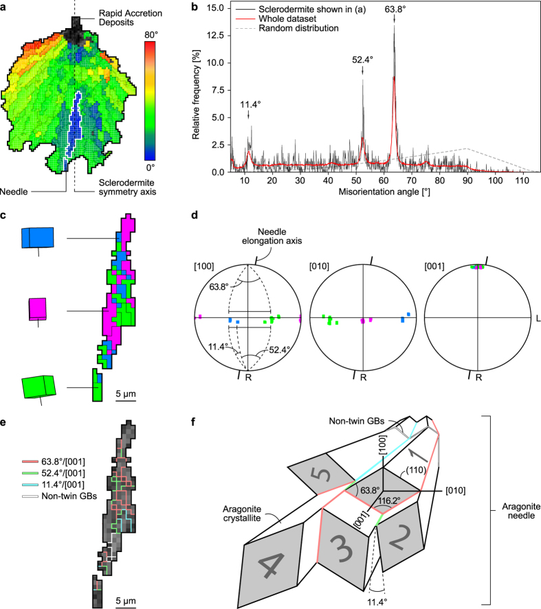
Crystallographic anatomy of sclerodermites. (a) EBSD cumulative misorientation map of the sclerodermite outlined in Fig. 2 showing the orientation of aragonite [001] axes with respect to the sclerodermite symmetry axis (dashed line). Only standard (i.e. non-twin) grain boundaries delimiting domains with misorientations >10° are indicated for clarity. The needle outlined in white has been selected for further investigation. (b) Diagram showing the non-random distribution of misorientation angles between the adjacent crystallites of the sclerodermite shown in (a). High relative frequencies are observed for misorientation angles of 11.4°, 52.4°, and 63.8°. (c) Trichromic EBSD map of the aragonite needle outlined in (a) illustrating the approximate orientation of the aragonite unit cell and [001] axes. (d) Pole figures of the needle shown in (c) displaying the strong clustering of aragonite [001] axes close to the needle elongation axis and the pseudo-hexagonal misorientation of [100] and [010] axes in a plane oriented normal to R. Pole figures are represented on lower hemisphere equal area projections. The radial and longitudinal growth directions of the corallite are indicated by R and L, respectively. Colour code as in (c). (e) EBSD twin boundary map of the needle shown in (c) displaying the misorientation angle/axis pairs between adjacent crystallites. Most of the grain boundaries are twin boundaries delimiting crystallites characterized by misorientations of 11.4°, 52.4°, and 63.8° around [001]. Note that non-twin grain boundaries are located in the bent section of the needle. (f) Sketch illustrating the angular and facial relationships between pseudo-hexagonally twinned crystallites within an aragonite needle. Misorientation angles between grains 1 & 2, 2 & 3, and 1 & 5 are 63.8°, 52.4° and 11.4°, respectively. Colour code as in (e).

