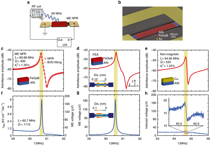
Fig. 1.

ME NPR device with gigantic ME coupling. a Schematic representation of the magnetoelectric (ME) nanoplate resonator (NPR) and the induced ME voltage measurement setup by using a high-frequency lock-in amplifier (HFLIA). The RF magnetic field (H RF) is generated by a RF coil. b Scanning electron microscopy (SEM) images of the fabricated the ME NPR. The red and blue areas show the suspended single nanoplate with FeGaB/AlN ME heterostructure and AlN anchors. The yellow area presents the RF ground-signal-ground electrode. c Admittance curve and Butterworth–van Dyke model fitting of the ME NPR with a resonance frequency (f r) of 60.68 MHz, quality factor (Q) of 930 and electromenchanical coupling coefficient (k t 2) of 1.35%. The inset shows the schematic of the cross-section of the ME heterostructure. d Finite element analysis (FEA) of ME NPR for the admittance amplitude. The inset shows the in-plane displacement of the nanoplate at resonance peak position and its coordinate system. e Admittance curve of a non-magnetic control sample which has a same device design as ME NPR. The inset shows the schematic of the device cross-section. f, ME coupling coefficient (left axis) and the induced ME voltage (right axis) versus the frequency of H RF excitation. g FEA of ME NPR for the induced ME voltage. The inset shows the in-plane displacement excited by H RF. h Induced voltage versus the frequency of H RF excitation for the non-magnetic device. The inset illustrates the zoomed-in view of the resonance peak area (red circle)
