Abstract
Statement of problem
Radiograph paralleling devices provide an excellent means of obtaining orthogonal radiographs for the evaluation of the fit of implant restorations. Unfortunately, the clinical applicability of such devices is a significant issue because access to the implant body must be obtained at each radiographic appointment.
Purpose
The purpose of the study was to investigate whether the fit or microgap at the implant-abutment junction could be more accurately and confidently assessed with a novel radiograph paralleling device that did not require access to the implant body once a proper registration index was made.
Material and methods
Microgaps of 0, 50, and 100 μm were introduced at the implant-abutment junction of a provisional implant crown in a manikin-typodont assembly. Dental assistants made 54 radiographs (18 per microgap) of the crown with and without a radiograph paralleling device; 9 clinicians then evaluated the standardized radiographs for the presence of misfit. The Cochran-Mantel-Haenszel test and the corresponding odds ratios were used to evaluate the effectiveness of the paralleling device in helping clinicians better assess misfit from the radiographs made.
Results
The use of the device led to a higher percentage of accuracy under all conditions (79.0% vs 70.4% at the 0-μm gap, 77.8% vs 16.1% at the 50-μm gap, and 100% vs 92.6% at the 100-μm gap); the improvement was statistically significant at the 50-μm gap (P<.001) and 100-μm gap (P=.049) but not at the 0-μm gap (P=.364). The odds ratio (95% confidence interval) of obtaining correct versus wrong answers with the device compared with without the device was 18.64 (7.94–43.77) at the 50-μm gap and 5.40 (0.25–114.25) at the 100-μm gap.
Conclusions
The study indicated that the paralleling device helped the clinician more accurately assess the implant-abutment junction with the 50- and 100-μm gaps.
Intraoral radiography can help assess the fit of an implant-abutment junction (IAJ) when it is properly used in conjunction with other evaluation modalities.1–4 Unfortunately, results of studies summarized in a review article have shown that improper alignment between the IAJ and the radiographic beam often hide prosthetic misfits.2 As the angulation of the radiographic tube diverges from the angle orthogonal (perpendicular) to the long axis of the implant, identifying the extent of IAJ opening becomes increasingly difficult.4–6 When the relative position of the implant to the film and radiographic collimator (tube head) is evaluated, the position of the collimator to the implant has been shown to be more critical than the relative relationship of the film to the implant.5 Moreover, clinicians routinely use the blurring or superimposition of the machined screw threads as a reference to discern radiographic tube misalignment; the diagnostic value of the radiographs is thus determined by the clarity of the threads on the film. However, because radiographic angulation can distort the crestal bone margin relative to the implant body while maintaining thread clarity, validating radiographs based on the presentation of implant threads is both inaccurate and subjective.7–10
Devices that allow direct access to the implant connection site have been used for many years and provide an excellent means of obtaining orthogonal radiographs.3,11–14 However, because these devices must obtain access to the implant at each radiographic appointment, clinical applicability is an issue. First, the prosthesis must be removed to allow the implant to be engaged; this is not a problem for retrievable screw-retained restorations, but it poses a significant challenge for cement-retained restorations.3,11–14 Second, abutment removal and reattachment at the IAJ is known to result in tissue changes and bone loss.15 A better means to achieve consistent radiographs without the need to remove the restoration is proposed.
By indexing the implant body to the adjacent dentition, the authors developed a novel radiograph paralleling device, the Precision Implant X-ray Relator and Locator (PIXRL), that could be attached to commercially available film holders.16 The use of the positioning device and the related clinical protocol were described in an earlier publication.16 In brief, the PIXRL was first positioned orthogonally to the implant with implant drivers or implant placement drivers, which allows a registration record to be made between the adjacent teeth and the positioned PIXRL. Because the occlusal relationship was indexed with the adjacent teeth, accurate radiographs could be made consistently without further removal of the implant prosthesis. The purpose of this study was to investigate whether the microgap at the IAJ could be more accurately and confidently assessed with radiographs made with the paralleling device in a clinically simulated model. The null hypothesis was that no difference would be found in the assessments made with the radiographs produced with the PIXRL versus the ones made in a routine clinical manner.
MATERIAL AND METHODS
A manikin-typodont assembly was used to simulate a dental patient. Three registered dental assistants were recruited from the postgraduate prosthodontics clinic and the faculty group practice at the University of California, San Francisco, School of Dentistry, to participate in the study. They made radiographs of the mandibular left first molar crown of the manikin with 3 microgaps at the IAJ (0, 50, and 100 μm). Nine prosthodontists subsequently evaluated the radiographs for the presence of microgaps.
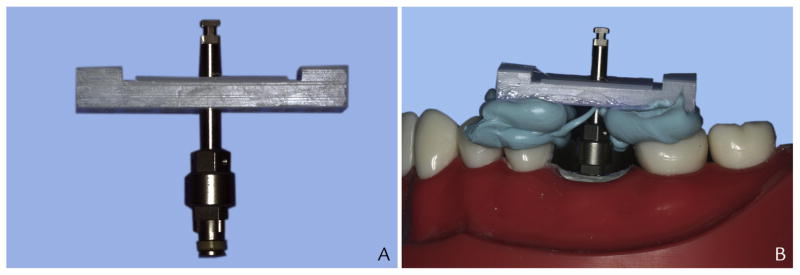
A dental implant (Replace Select Tapered TiUnite WP 5.0×11.5 mm; Nobel Biocare) was buccally inclined and stabilized with Type II fast set dental plaster (Snow White Plaster no. 2; Kerr Dental Laboratory Products) at the mandibular left first molar site on the typodont (32 Teeth Hard Gingivae Type; Kilgore Intl). The remaining plastic dentition was intact (Fig. 1). The orientation and angulation of an implant placement is often limited by the morphology of the residual ridge.17 Thus, the implant in this study was buccally inclined to simulate a clinical situation. A screw-retained provisional implant restoration was fabricated with a final abutment (WP Gold Adapt abutment, internal tri-channel connection, engaging; Nobel Biocare) and composite resin (Herculite XRV Micro-hybrid Composite; Kerr Corp). The implant crown was fabricated with anatomic anatomy and occlusion (Fig. 2). The PIXRL was indexed to the implant and the adjacent dentition with an implant placement driver (Implant Driver, NobelReplace, Short WP; Nobel Biocare) and a polyvinyl siloxane registration material (Blu-Mousse; Parkell) (Fig. 3). The index was then connected to a conventional film-holding device (Rinn XCP; Dentsply Rinn).
Figure 1.
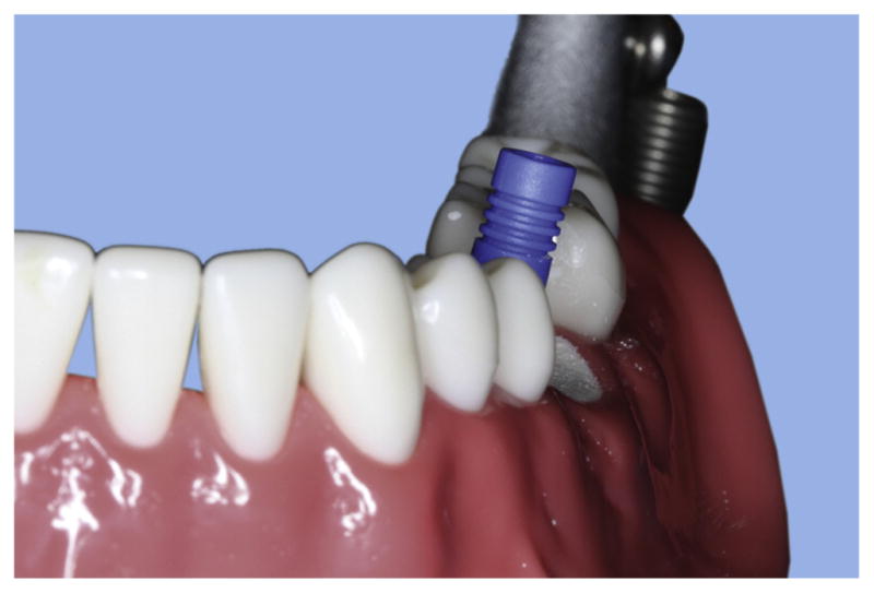
Indicated by unmodified definitive abutment, implant body was positioned in typodont with buccal inclination at mandibular left first molar site.
Figure 2.
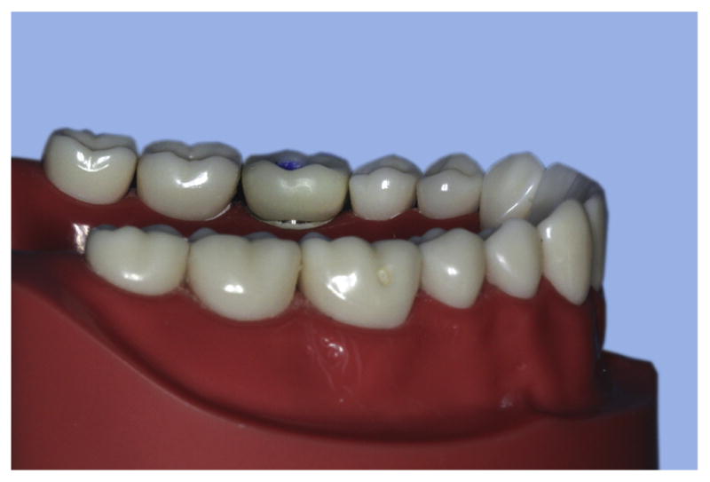
Implant crown was fabricated with anatomic contour and occlusion by building composite resin on modified definitive abutment.
Figure 3.
Precision Implant X-ray Relator and Locator (PIXRL) device assembly. A, Implant placement driver was oriented perpendicularly to PIXRL index. B, Assembly was indexed to implant body and adjacent dentition with placement driver and occlusal registration material.
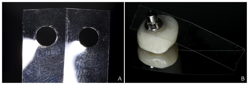
Gaps of 0, 50, and 100 μm were formed by inserting 0, 1, or 2 thicknesses of Mylar matrix strips (Henry Schein) at the IAJ during different phases of the experimental protocol. A 4-mm-diameter circular hole was made at the center of each Mylar matrix strip to ensure an even surface contact with the implant and abutment under-surface when inserted (Fig. 4). Gap thicknesses of 50 μm and 100 μm were selected because previous studies indicated that clinicians had difficulty detecting an interface opening that ranged from 50 to 150 μm as the angulation of the radiographic tube head increased up to 20 degrees.4,5
Figure 4.
Mylar strip–implant crown interface. A, Each Mylar strip had 50-μm thickness. B, A 4-mm-diameter hole was created and even surface contact between Mylar strip and intaglio surface of implant crown was ensured.
After each microgap condition was created, the implant crown was tightened to 35 Ncm according to the recommendation of the manufacturer for definitive restorations. The screw access channel was filled with poly-tetrafluoroethylene tape and composite resin to simulate a clinical screw-retained crown delivery. Once properly prepared, the typodont was then mounted onto a manikin head (NIS-SIM Manikin Head; Kilgore International) for clinical simulation. The typodont was set to close with general-purpose rubber bands and paper clips (Fig. 5). A digital x-ray machine (Kodak 2200 Intraoral X-ray System; Carestream Dental) was tested and preset at 70 Kv and 7 mA to provide optimal contrast and brightness for the experimental model.
Figure 5.
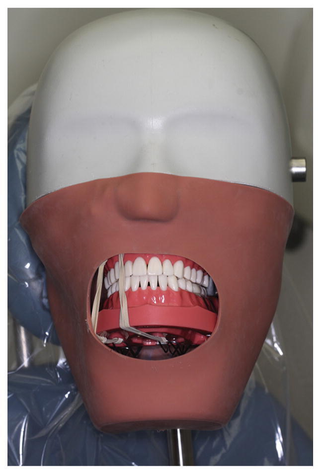
Manikin with default jaw closure.
Under each of the 3 gap conditions (0, 50, and 100 μm), the dental assistants made 3 radiographs by using a commercially available film-holding device (Rinn XCP; Dentsply Rinn) in their usual manner (Fig. 6). They were then instructed to use the same film holder with the indexed PIXRL attached to make 3 additional radiographs under each condition. The additional instruction for the PIXRL condition was restricted. The registration record on the PIXRL device was placed against the adjacent teeth without moving the radiograph sensor.
Figure 6.
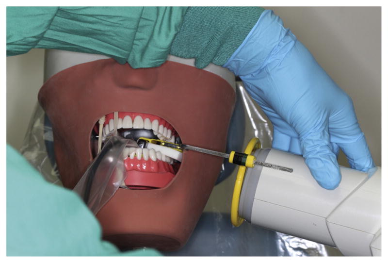
Assistants made radiographs in clinically simulated model.
Between making each radiograph, the film-holding assembly; the radiographic tube; and the cotton rolls, cotton pads, and gauze were returned to their original position before the assistants proceeded. The assistants were free to use cotton rolls, cotton pads, and gauze to stabilize the occlusion or film-holding assembly as necessary. In summary, each assistant made 18 radiographs. Under each misfit condition (0, 50, and 100 μm), 3 radiographs were made with the PIXRL index and 3 without the PIXRL index. Altogether, 54 radiographs were collected from the 3 assistants for evaluation.
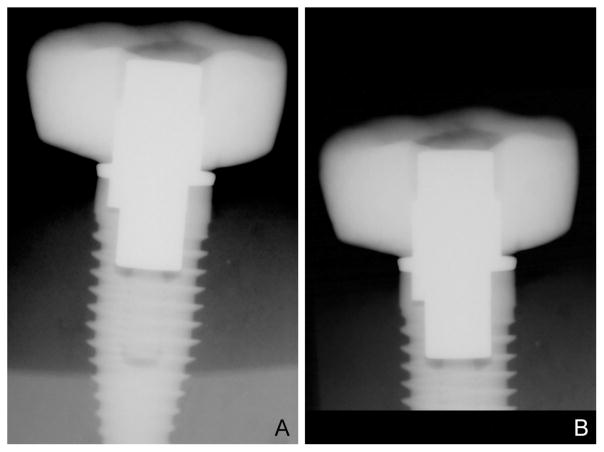
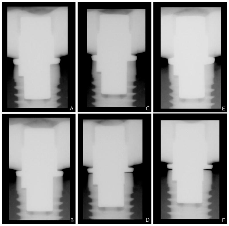
The radiographs were exported from the digital software (Emago/Advanced, v5.6.4; Exan Academic) as Joint Photographic Experts Group (JPEG) files. Without adjusting the contrast or brightness of the original images, these were cropped, resized, and positioned in the center of each slide in the presentation software (PowerPoint for Mac 2011 v14.1; Microsoft Corp) for standardization (Fig. 7). The display sequence of the 54 radiographs was then randomized with a spreadsheet function (Excel for Mac 2011 v14.1.0; Microsoft Corp). After randomization, the slides were reorganized, numbered, and assembled in a presentation. A questionnaire, numbered 1 through 54, also was prepared, formatted with the question, “Is there a misfit between the implant abutment and the implant?” and the answer choices, “misfit, no misfit, unsure.” The presentation and the questionnaire were presented to each of the 9 evaluators. A collective sample of edited radiographs from 1 assistant was provided for visualization (Fig. 8).
Figure 7.
Standardization of radiographs. A, Unaltered digital radiograph. B, Each radiograph was cropped, resized, and centrally positioned for standardization of presentation.
Figure 8.
Representative radiographs made by assistant. A, At 0 μm without Precision Implant X-ray Relator and Locator (PIXRL). B, At 0 μm with PIXRL. C, At 50 μm without PIXRL. D, At 50 μm with PIXRL. E, At 100 μm without PIXRL. F, At 100 μm with PIXRL.
The frequencies and percentages of correct, incorrect, and unsure assessments of the radiographs were compiled. The Cochran-Mantel-Haenszel test was used to assess the effectiveness of the PIXRL in helping clinicians evaluate the radiographic IAJ with 0-, 50-, and 100-μm microgaps (α=.05). The corresponding odds ratios (OR) and their 95% confidence intervals were computed by following the Woolf formula for log OR.18 If any empty cells were found in a contingency table, then each cell (nij) in the contingency table was replaced by nij + 0.5 in estimating OR and its standard error for 95% confidence interval.19
RESULTS
Nine evaluators completed a total of 81 misfit assessments. The frequencies and percentages of misfit, no misfit, or unsure responses, and the results of the Cochran-Mantel-Haenszel test are summarized in Table I. The ORs of the various microgap comparisons are summarized in Table II. Under the control condition (0-μm misfit), 70.4% of the misfit assessments (57 of 81) were correct in the no PIXRL group and 79% of the assessments (64 of 81) were correct in the PIXRL group. Under the 50-μm misfit condition, 16.1% of the assessments (13 of 81) were correct in the no PIXRL group, and 77.8% (63 of 81) were correct in the PIXRL group. Compared with no PIXRL, ratings with PIXRL had approximately 19 times the odds of being correct versus being wrong and approximately 18 times the odds of being correct versus being unsure (Table II). The difference was statistically significant (P<.001).
Table I.
Comparison of total number of misfits, no misfit, and unsure answers obtained from radiographs made with or without PIXRL device
| Misfit Size | Misfit (%) | No Misfit (%) | Unsure (%) | Total | Pa |
|---|---|---|---|---|---|
| 0 μm | .364 | ||||
| No PIXRL | 7 (8.6) | 57 (70.4) | 17 (21.0) | 81 | |
| PIXRL | 4 (4.9) | 64 (79.0) | 13 (16.1) | 81 | |
| Total | 11 | 121 | 30 | 162 | |
|
| |||||
| 50 μm | <.001 | ||||
| No PIXRL | 13 (16.1) | 50 (61.7) | 18 (22.2) | 81 | |
| PIXRL | 63 (77.8) | 13 (16.0) | 5 (6.2) | 81 | |
| Total | 76 | 63 | 23 | 162 | |
|
| |||||
| 100 μm | .049 | ||||
| No PIXRL | 75 (92.6) | 2 (2.5) | 4 (4.9) | 81 | |
| PIXRL | 81 (100) | 0 (0) | 0 (0) | 81 | |
| Total | 156 | 2 | 4 | 162 | |
PIXRL, Precision Implant X-ray Relator and Locator.
Cochran-Mantel-Haenszel test was used to compare ratings between radiographs with or without PIXRL device, conditional on raters (clinicians).
Table II.
Odds ratio (95% CI) of getting correct vs wrong answers and of getting correct vs unsure answers with PIXRL vs with no PIXRL under 3 misfit conditions
| Misfit Condition | PIXRL vs. No PIXRL*
|
|
|---|---|---|
| Correct vs Wrong | Correct vs Unsure | |
| 0 μm | 1.96 (0.55–7.06) | 1.47 (0.66–3.29) |
| 50 μm | 18.64 (7.94–43.77) | 17.45 (5.49–55.48) |
| 100 μm | 5.40 (0.25–114.25) | 9.72 (0.51–183.50) |
OR, odds ratio; PIXRL, Precision Implant X-ray Relator and Locator; CI, confidence interval.
OR and 95% CI were computed based on Woolf formula from contingency tables.
Under the 100-μm misfit condition, the result from the Cochran-Mantel-Haenszel test (P=.049) demonstrated a statistically significant difference in accuracy between the no PIXRL and the PIXRL groups (Table I). Specifically, 92.6% of the assessments (75 of 81) were correct in the no PIXRL group and 100% (81 of 81) were correct in the PIXRL group. Compared with no PIXRL, ratings with PIXRL had approximately 5 times the odds of being correct versus being wrong and approximately 10 times the odds of being correct versus being unsure (Table II).
DISCUSSION
The findings in the present study indicated that the use of the PIXRL device could lead to a higher percentage of accurate assessment under all conditions, and the improvement was statistically significant at 50 μm and 100 μm but not at 0 μm. The statistical analysis at the 0-μm microgap demonstrated no significant difference in the evaluations of radiographs made with and without the PIXRL device. This was expected because the 0-μm microgap was the control and had no misfit at the IAJ; the presence of radiographic tube angulation could not mask any misfit. When following the same logic and regardless of whether or not the radiograph paralleling device was used, clinicians incorrectly identified the IAJ as containing a misfit up to 30% of the time; this suggests that clinicians might not have a full understanding of the radiographic presentation of a well-fitted IAJ. The prevalence of incorrect assessment (n=41) is a topic for future investigation.
The statistical analysis demonstrated significant difference in the number of correct evaluations from radiographs made with or without the PIXRL device under both 50 μm and 100 μm misfit conditions. When the radiographic beam passes through the IAJ at an angle greater than 0 degrees, the geometric model confirms that a quantifiable amount of opening can be hidden because the only radiation of diagnostic value not blocked is near the edges of the abutment and the head of the implant. Radiographically, such detectable edges between the abutment and the head of the implant body diminish as the beam diverges.5 This is why identifying a misfit on the radiograph becomes increasingly difficult as the beam divergence increases. Although this study examined the accuracy of fit assessment without controlling for tube angulation, Ormaechea et al4 investigated the relationship of controlled radiographic tube angulation and IAJ gap assessment by clinicians in a laboratory setting. Consistent with the concept described, as the gap at the IAJ increased from 50 μm to 100 μm, the accuracy of the assessment by clinicians decreased from 62% to 0% when the radiographic beam diverged from 10 to 15 degrees.4
In addition to demonstrating the difference in evaluation accuracy, this study revealed that clinicians were able to assess for misfit more confidently when a radiograph paralleling device was used. The number of unsure answers was effectively reduced with the use of PIXRL in both misfit conditions. This was critical to investigate because uncertainty from a clinician about the diagnostic value of a radiograph may lead to remaking radiographs in a clinical setting and increase a patient’s exposure to radiation. Further evaluation is required to establish an association between the mental assessment of a poor radiograph by a clinician and the actual number of requests for a remake.
To the authors’ knowledge, this was the first study to examine the assessment of misfit at the IAJ in a simulated clinical situation. In this experimental model, the dental assistants were found to use cotton rolls, cotton pads, and/or gauze to stabilize the dentition inconsistently when making radiographs. The collimator ring on the film holder also was misaligned against the radiographic tube head on numerous occasions. Without controlling for operator error and evaluator bias, this study demonstrated that a radiograph paralleling device such as the PIXRL could help assistants reduce the radiographic tube angulation and allow evaluators to assess implant prosthetic misfit more confidently and accurately by using radiographs. Investigating the effect of a microgap less than 50 μm was not considered because the resolution of the existing digital x-ray system was limited to 14 line pairs per 35.7 μm. Although it was possible to introduce a 21- or 42-μm gap by using articulating film (Accufilm; Parkell) at the IAJ, the marginal discrepancy might be too small for this particular x-ray system to detect predictably.
Anatomic limitation and psychologic factors in human participants could not be addressed in a manikin model. The radiographs were made without time constraint and patient management issues. In addition, the PIXRL has limitations because the use of orthogonal radiographs usually is confined to single implant sites. This is simply because the ability of the surgeon to perfectly align multiple implants parallel to one another is difficult, if not impossible. In situations in which multiple implants are linked by the prosthesis, the ability to detect misfit at each individual IAJ would require the PIXRL to be fabricated for each implant site. In an edentulous site, enhanced stability may be achieved by extending the index registration plate of the PIXRL on the dentate side.
To simulate clinical situations, the assistants were given the freedom to align the radiographic tube without additional instructions. The inconsistent technique might have subsequently rendered some of the radiographs nondiagnostic. However, because the assistants were blinded to the experiment design and the misfits that were introduced in the implant crown, the likelihood of making technical errors in radiography with and without the PIXRL device was equivalent. Furthermore, because the assistants made 3 radiographs under each condition, the impact of operator error was minimal given the statistical significance of the overall findings.
The purpose of this study was not to address the difference in bias among the evaluators. However, because the sequence of the misfit and control radiographs was randomized in the presentation, the bias within each evaluator was consistent throughout the assessment. Finally, because the study was conducted in a postgraduate prosthodontic clinic, where the participants were affiliated with the university, the variation in the assistants’ ability to make diagnostic implant radiographs and the bias of the evaluators might not have reflected the general pattern beyond the academic institution.
CONCLUSION
Under the control (0 μm) condition, the PIXRL device did not allow radiographs to be assessed more accurately. Under the 50- and 100-μm misfit conditions, the implant IAJ may be more accurately assessed with radiographs made with the PIXRL device than without the device; the PIXRL device also allows clinicians to evaluate misfits more confidently. The use of a radiograph paralleling device is essential in making diagnostic radiographs for the assessment of implant prosthetic misfit.
Clinical Implications.
The use of a radiograph paralleling device is critical in making diagnostic radiographs to assess implant prosthetic misfit. The proposed device provides an effective and simple way of detecting microgaps up to 100 μm in applicable clinical situations.
Acknowledgments
The project was partially supported by the Department of Preventive and Restorative Dental Sciences, University of California San Francisco. Dr Jing Cheng’s work was partially supported by grant U54DE019285 from the National Institute of Dental and Craniofacial Research.
Footnotes
Second place winner of the Graduate Prosthodontic Research Competition at the Pacific Coast Society for Prosthodontics, 78th Annual Meeting, Anchorage, Alaska, June 2013.
References
- 1.Yanase RT, Binon PP, Jemt T, Gulbransen HJ, Parel S. Current issue form. How do you test a cast framework for a full arch fixed implant supported prosthesis? Int J Oral Maxillofac Implants. 1994;9:471–4. [Google Scholar]
- 2.Kan JYK, Rungcharassaeng K, Bohsali K, Goodacre CJ, Lang BR. Clinical methods for evaluating implant framework fit. J Prosthet Dent. 1999;81:7–13. doi: 10.1016/s0022-3913(99)70229-5. [DOI] [PubMed] [Google Scholar]
- 3.Cox JF, Pharoah M. An alternative holder for radiographic evaluation of tissue-integrated prostheses. J Prosthet Dent. 1986;56:338–41. doi: 10.1016/0022-3913(86)90016-8. [DOI] [PubMed] [Google Scholar]
- 4.Ormaechea MB, Millstein P, Hirayama H. Tube angulation effect on radiographic analysis of the implant-abutment interface. Int J Oral Maxillofac Implants. 1999;14:77–85. [PubMed] [Google Scholar]
- 5.Cameron SM, Joyce A, Brousseau JS, Parker MH. Radiographic verification of implant abutment seating. J Prosthet Dent. 1998;79:298–303. doi: 10.1016/s0022-3913(98)70241-0. [DOI] [PubMed] [Google Scholar]
- 6.Weyns W, De Boever J. Radiographic assessment of the marginal fit of cast restorations. J Prosthet Dent. 1984;51:485–9. doi: 10.1016/0022-3913(84)90298-1. [DOI] [PubMed] [Google Scholar]
- 7.Benn DK. Estimating the validity of radiographic measurements of marginal bone height changes around osseointegrated implants. Implant Dent. 1992;1:79–83. [PubMed] [Google Scholar]
- 8.Sewerin IP. Comparison of radiographic image characteristics of Brånemark and IMZ implants. Clin Oral Implants Res. 1991;2:151–6. doi: 10.1034/j.1600-0501.1991.020308.x. [DOI] [PubMed] [Google Scholar]
- 9.Sewerin IP. Estimation of angulation of Brånemark titanium fixtures from radiographic thread images. Clin Oral Implants Res. 1991;2:20–3. doi: 10.1034/j.1600-0501.1991.020102.x. [DOI] [PubMed] [Google Scholar]
- 10.Sewerin IP. Errors in radiographic assessment of marginal bone height around osseointe-grated implants. Scand J Dent Res. 1990;98:428–33. doi: 10.1111/j.1600-0722.1990.tb00994.x. [DOI] [PubMed] [Google Scholar]
- 11.Basquill PJ, Steflick DE, Brennan WA, Horner J, Van Dyke TE. Evaluation of the effects of diagnostic radiation on titanium dental implant osseointegration in the micropig. J Periodontol. 1994;65:872–80. doi: 10.1902/jop.1994.65.9.872. [DOI] [PubMed] [Google Scholar]
- 12.Payne AGT, Solomons YF, Lownie JF. Standardization of radiographs for mandibular implant-supported overdentures: review and innovation. Clin Oral Impl Res. 1999;10:207–319. doi: 10.1034/j.1600-0501.1999.100407.x. [DOI] [PubMed] [Google Scholar]
- 13.Naffah N, Johann CJ. A modified periapical radiographic holder used for standardized implant assessment. J Prosthet Dent. 2004;91:398. doi: 10.1016/j.prosdent.2003.12.020. [DOI] [PubMed] [Google Scholar]
- 14.Galasso L. Proposed method for the standardized measurement of marginal bone height on periapical radiographs with the Branemarrk System. Clin Implant Dent Relat Res. 2000;2:147–51. doi: 10.1111/j.1708-8208.2000.tb00005.x. [DOI] [PubMed] [Google Scholar]
- 15.Hermann F, Lerner H, Palti A. Factors influencing the preservation of the periimplant marginal bone. Implant Dent. 2007;16:165–75. doi: 10.1097/ID.0b013e318065aa81. [DOI] [PubMed] [Google Scholar]
- 16.Lin KC, Wadhwani CP, Sharma A, Finzen F. A radiograph positioning technique to evaluate prosthetic misfit and bone loss around implants. J Prosthet Dent. 2014;111:163–5. doi: 10.1016/j.prosdent.2013.06.016. [DOI] [PubMed] [Google Scholar]
- 17.Sethi A, Kaus T, Sochor P. The use of angulated abutments in implant dentistry: five-year clinical results of an ongoing prospective study. Int J Oral Maxillofac Implants. 2000;15:801–10. [PubMed] [Google Scholar]
- 18.Woolf B. On estimating the relation between blood group and disease. Ann Human Genet. 1955;19:251–3. doi: 10.1111/j.1469-1809.1955.tb01348.x. [DOI] [PubMed] [Google Scholar]
- 19.Gart JJ. Alternative analyses of contingency tables. J Royal Stat Soc Series B (Methodol) 1966;28:164–79. [Google Scholar]


