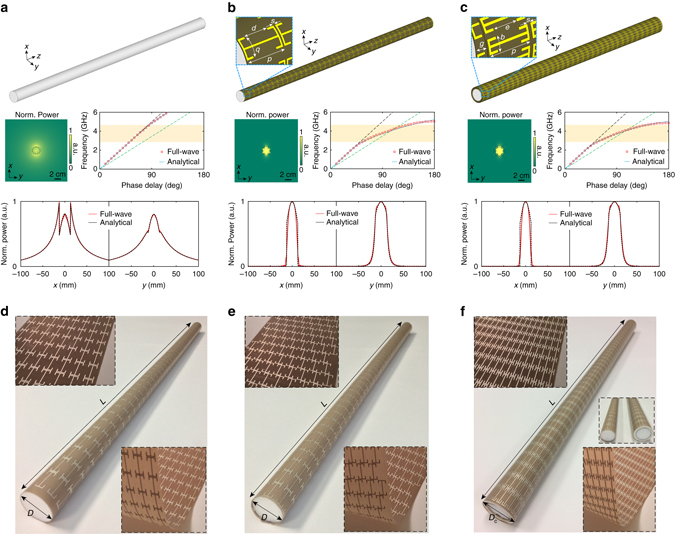
Fig. 1.

A sub-wavelength dielectric rod waveguide coated by conformal metasurface layers. Configuration, dispersion curves, normalized power distribution in the x-y plane at 3.4 GHz, and normalized power cuts along the x- and y-axis at 3.4 GHz of a a bare Teflon rod waveguide with ε r = 2.1, b the same Teflon rod waveguide coated by the metasurface guiding layer, and c the same Teflon rod waveguide coated by the metasurface guiding and cloaking layers. For the dispersion curves, the dashed gray and dashed green lines are the light lines of free space and Teflon, respectively. The highlighted region is from 2.8 to 4.59 GHz. The photographs of the fabricated and assembled samples are shown in d for the Teflon rod coated by the metasurface guiding layer, e for the Teflon rod coated by the metasurface guiding layer with twisting perturbation, and f for the Teflon rod coated by the metasurface guiding and cloaking layers. The insets of d–f show enlarged views of the ultrathin flexible metasurfaces. The dimensions are: b = 3.9, d = 8.5, D = 25.4, D c = 33.4, e = 8.5, g = 4, L = 600, p = 15, s = 0.5, all in millimeters. The substrate material is Taconic TLY-5 (ε r = 2.2, tanδ = 0.0009) with a thickness of 0.1 mm
