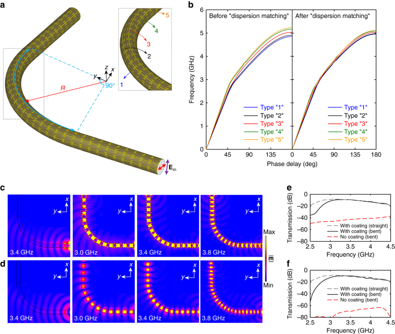
Fig. 6.
A right-angle dielectric rod waveguide bend with a single-layer metasurface coating. a Configuration of the right-angle Teflon rod waveguide bend coated by the metasurface guiding layer with an inhomogeneous distribution of unit cells in the bending section. The inset shows the enlarged view of the bending section, with the 5 types of unit cells labeled out. b Simulated dispersion curves for the five types of unit cells before and after “dispersion matching”. The dimensions for unit cells in progressive order from type “1” to type “5” are: p = 14, 14.3, 15, 15.7, 16 mm, q = 7.05, 6.75, 6.5, 6.2, 6 mm, and s = 0.35, 0.37, 0.5, 0.7, 0.75 mm. Snapshots of the electric field distribution of a bare and the coated Teflon rod waveguide bending in the c electric and d magnetic field plane. The simulated transmission between the transmitting and receiving probes for the bare and coated Teflon rod waveguide bending in the e electric and f magnetic field plane, as well as for the straight coated Teflon rod waveguide

