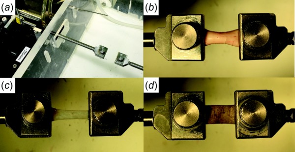
Fig. 2.

Tensile loading apparatus and specimen clamping. (a) The Linear motor on the left was connected to a strain gauge transmitting its measured tensile force through a frictionless air bearing and cylindrical shaft to the moveable specimen clamp to which one end of the specimen was affixed in an environmentally controlled chamber at right. The other clamp at right was rigidly anchored at the opposite end of the specimen. ON (b), ON sheath (c), and sclera (d) were similarly clamped at each end.
