
Figure 1.
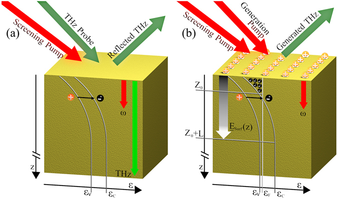
A schematic of the excitation geometry of the InAs surface, depicting the relevant physical interactions, for OPTP (a) and OPRE (b) Band diagrams along the depth direction z, with the valence and conducting energies ε v and ε c are indicated in both cases. (a) A screening pump induces free electron-hole pairs, such free-carriers are generated mostly within the skin depth of the pump, indicated with the red arrow. The concentration of free-carriers changes the reflectivity of a THz probe. The skin depth of the THz is indicated in green. (b) The surface field is indicated by the gradated arrow, resulting from the balancing of the surface charges (plus signs on the top) and localised free-electrons in the surface accumulation region (0 < z < Z 0) and the spatial charge in the depleted (Z 0 < z < Z 0 + L) region. Free-electrons in the conduction band are indicated by black dots with minus signs, while ε F indicates the Fermi level. The THz is generated by the interaction of the generation pump with the surface field, while the screening pump also generates free-carriers in this case, effectively screening the surface field .