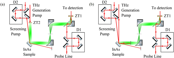
Figure 2.

Experimental setup for OPTP (a) and OPRE (b) diagnostics. The red and green beam paths denote the 800 nm optical and THz beam paths respectively. For both setups, the THz field is measured with a standard electro-optic detection36, which retrieves the change of polarisation of an optical probe of energy (~1 µJ) inside a ZnTe detection crystal (ZT1) due to the THz field. A delay line D1 control the delay t d between the THz and the optical probe and allows for the reconstruction of the THz waveform. (a) The THz is generated by a ZnTe crystal (ZT2) converting a generation pump with a pulse energy of 1 mJ. (b) The THz is directly generated on the sample under investigation (InAs sample) converting a generating pump with energy 0.1 mJ. In both configurations, the relative angle between the screening pump beam and the THz probe beam (a) or optical generating pump (b) is 11.9°. The p-polarised screening pump energy was 1 mJ and 0.1 mJ for (a) and (b) respectively. The delay between the screening optical pulse and the generating optical pulse τ s is controlled with the delay line D2 in both cases.
