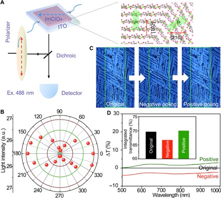
Fig. 3. Electro-optic effect of ImClO4 thin films.

(A) Diagram of the apparatus used to determine the angle-dependent polarization. The light-matter interaction is strongest when the polarization vectors of the ImClO4 thin film are directed parallel to the [2,,0] direction. (B) Angle-dependent transmitted light intensity of ImClO4 thin film. (C) Optical images of negatively and positively poled ImClO4 thin films. Green rectangles represent the electrode area. (D) Comparison of the transmission spectra of the original and negatively and positively poled states. The inset shows the transmittance of the ImClO4 thin film on ITO substrate at three different states.
