
Fig. 5.
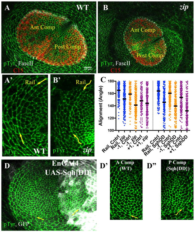
Alignment requires Myosin II function. A, B) Late third instar leg disks labeled with anti-PTyr (green), C15 (red) and Fasc II (white). A) Sibling control; anterior and posterior compartments are indicated. A′) A sector of the A compartment including rail is shown at increased magnification (pTyr channel only). The curving rail interface is highlighted by yellow arrows. B) zip mutant disk. B′) A sector of the A compartment including rail is shown at increased magnification (pTyr channel only). The wiggly appearance of the rail interface is obvious, and highlighted by wiggly yellow arrows. C) Scatter plot of alignment angles (in degrees), with bar representing the median value. The left half presents angles measurements for control (heterozygous siblings) versus zip2/zipEbr mutants, for the rail (blue), the −1 (orange) and the +1 (purple) interfaces. The right half of the scatterplot presents angle measurements for control (anterior compartment) versus cells expressing Sqh. DD (posterior compartment), for the rail (blue), the −1 (orange) and the +1 (purple) interfaces. D) Representative disk from En-GAL4 > UASGFP, UAS-Sqh. DD larva, stained for pTyr (green) and GFP (white). The yellow arrows draw attention to the rail interfaces within the anterior or posterior compartment, which are featured at higher magnification in D′, D″. D′) Control cells (anterior compartment), arrow points along rail interface. D″) Cells expressing Sqh. DD (posterior compartment), wiggly arrow points along rail interface. Scale bar applied to A′, B′, D′, D″ would be 5 μm.