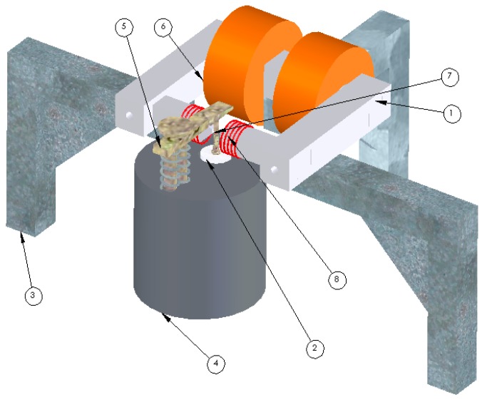
Figure 4.
1. Electromagnet’s poles; 2. Lower contact and ac load system; 3. Electromagnet support; 4. BerlinCourt d33 measurement system; 5. Top sample contact; 6. DC coils of the electromagnet; 7. Sample; 8. AC coils generating the AC magnetic field. Image developed by the authors and a CAD engineer at NPL as part of the Multiprobe MET 2.1 Project.

