
FIGURE 1.
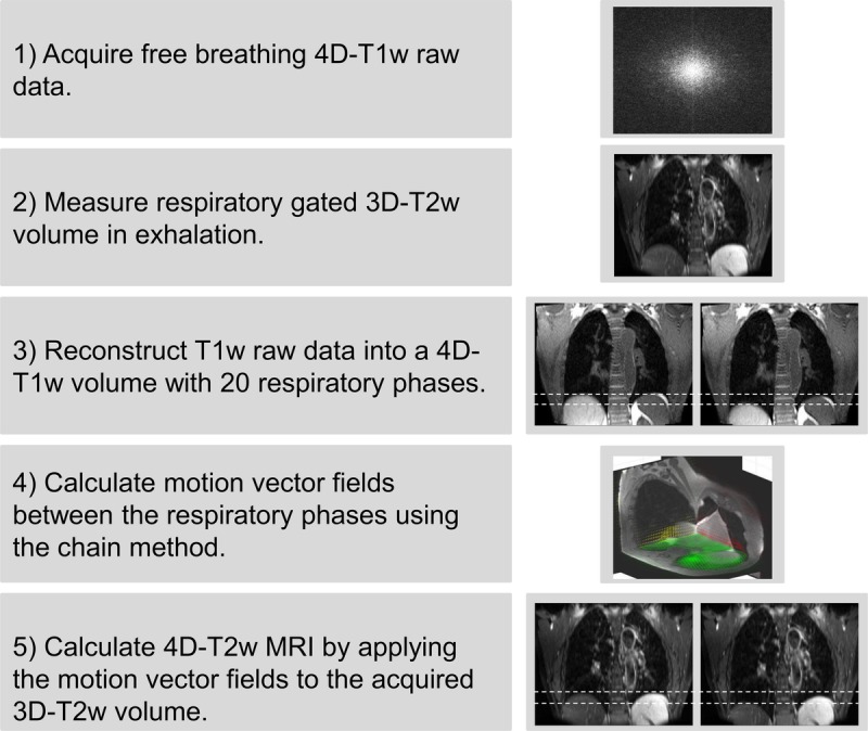
A visual overview of the motion vector field projection method. Note that the green, red, and yellow arrows in step 4 display the motion vector fields corresponding to the shown axial, coronal, and sagittal planes. Dashed white lines aid visualization of the diaphragm position on T1w and T2w MRI.