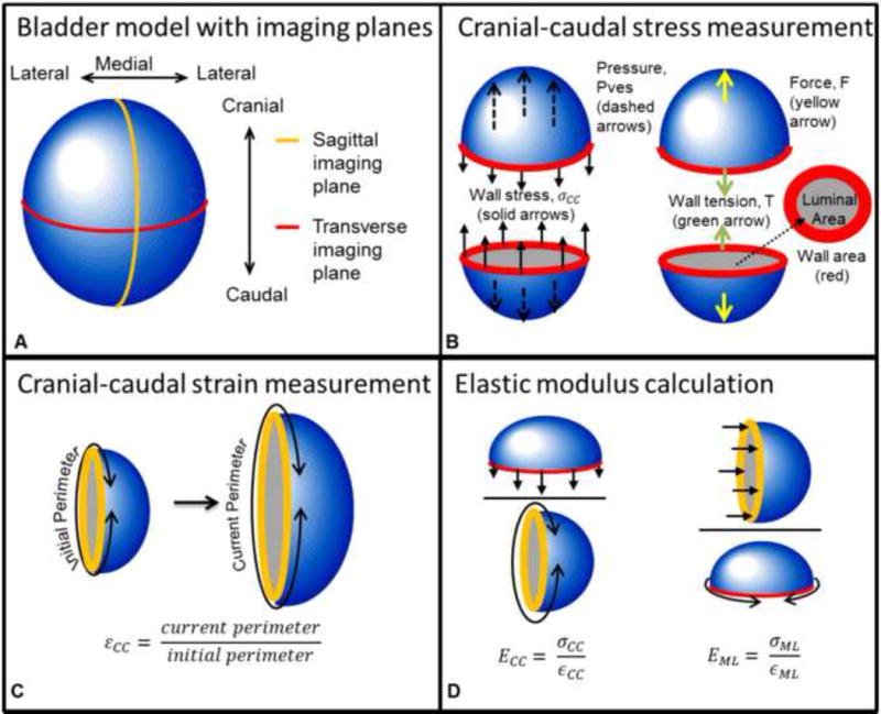
Figure 2.

Bladder model used to demonstrate calculation of tension-based wall compliance. A) The bladder with transverse and sagittal cross-sectional planes and anatomical directions. B) Pressure (Pves, blue line from Fig. 1) in the cranial-caudal direction (dashed arrows) acts on the luminal area (gray) in the transverse plane and is opposed by the wall stress (solid arrows) acting on the wall cross-sectional area (red). Pves results in force, F, which is opposed by wall tension, T. C) Strain was calculated as the ratio of the current perimeter divided by the initial perimeter. D) Elastic modulus was calculated as the current stress divided by the current strain in each direction.
