
Figure 1.
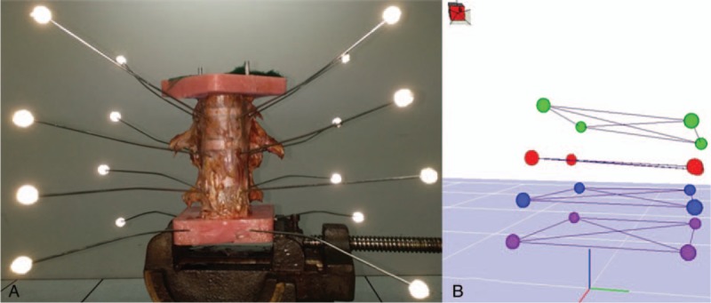
Experimental setup. Motion was applied to the thoracolumbar spine specimens (T11–L3). The cranial (T11) and caudal (L3) were mounted in Plexiglas casts. The caudal was fixed to the table vice, and the cranial was fixed to the loading jig. Axial rotation and flexion–extension were applied in the same direction. Lateral bending required a 90° rotation (A). To capture these motions, 4 fluorescent markers were inserted in each vertebral plane and a 3-dimensional model was reconstructed through computer software (B).