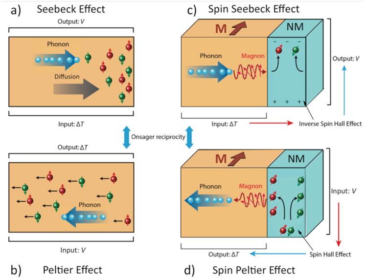
Figure 8.

Schematic illustrations of (a) conventional Seebeck effect with temperature difference ΔT applied to a metal (hot end on left), electric field E (voltage V) generated along ΔT and (b) conventional Peltier with applied voltage generating a temperature difference. The conventional effects in (a) and (b) are dominated by thermally-induced asymmetric diffusion (indicated by large grey diffusion arrow) of both spin up (red) and spin down (green) electrons in (a), or voltage-induced drift (small black arrows for both spin up and spin down electrons) in (b), though a phonon flux is always present (as indicated schematically) as well as a magnon flux, which can contribute via momentum transfer in drag effects. These are compared to (c) spin Seebeck effect with ΔT applied to a ferromagnet with M into the page (either metal or insulator) which produces a spin current and (d) the reciprocal spin Peltier effect. When connected to a non-magnetic metal (NM, blue), ΔT induces a spin current that is converted into a vertical electric field Eishe and VISHE due to the inverse spin Hall effect. In (c) and (d), magnons in the ferromagnet are shown producing the spin current, but different chemical potentials for up and down spins in a metallic ferromagnet would also produce a spin current if (and only if) the spin diffusion length were comparable to the sample length. For spin Seebeck and spin Peltier effects, clearly distinguishable only in magnetic insulators, schematics show current understanding of the physical mechanism, which is thermally-driven magnons that cause incoherent spin pumping at the interface. Adapted from [Heremans and Boona, 2014].
