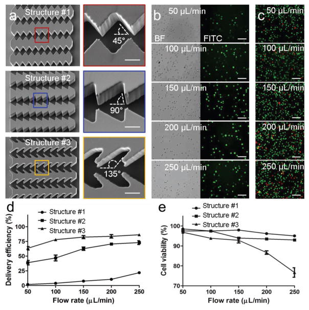
Figure 2.
Optimization of delivery structures. a) SEM images of three delivery structures. Scale bar, 10 μm. b) Images of MDA-MB-231 cells delivered with FITC-dextran (70K) at different flow rates. Scale bar, 100 μm. c) Images of live/dead staining of the delivered cells. Green dots represent live cells and red dots indicate dead cells. Scale bar, 100 μm. d) Delivery efficiency by different structures and flow rates. e) Cell viability of the delivered cells by different structures and flow rates.

