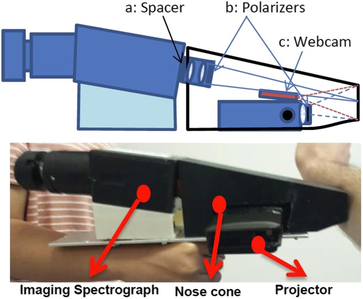
FIG. 3.
Clinical imaging head: Top figure shows the imaging head schematic, identifying the (a) brass spacer that modifies the field of view and focal length of the standard 35 mm marco-lens, (b) locations of the crossed polarizers to reject specular reflection, and (c) the endoscopic webcam that localizes the relative positions of projector and slit imaging spectrograph, relative to the tissue. Bottom image depicts the physical device, indicating the relative placements of the imaging spectrograph to the projector and nose cone.

