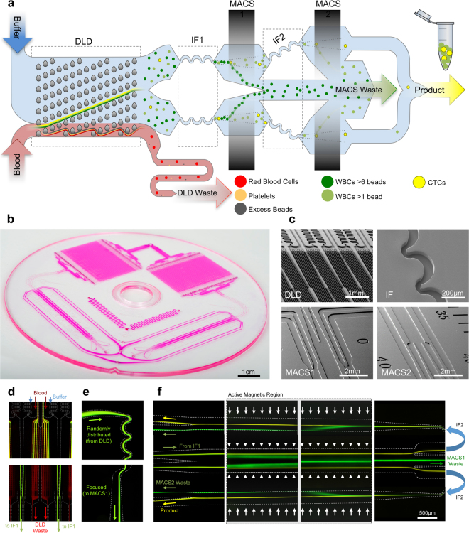
Figure 1.
Device and Process Flow - (a) Linearized schematic of the monolithic chip and how cells are processed. (b) Photograph of a single chip filled with dye. (c) Scanning electron micrographs of important locations on the chip, top left: DLD structures, top right: Inertial focusing units, bottom left: MACS1 inlet merge and MACS 2 outlet, and bottom right MACS2 inlet and MACS1 outlet split. Blood pre-labeled with antibodies and magnetic beads targeting white blood cells and buffer enter the device and first go through a deterministic lateral displacement (DLD) device that separates nucleated cells from the red blood cells, platelets and unbound magnetics beads. These cells are then accelerated through an inertial focusing device (IF1) that causes the alignment of the cells without the addition of a sheath flow. These aligned cells merge into a single channel and then pass through a magnetic field where the high gradient forces magnetically tagged cells towards the center of the channel (MACS1). This channel then splits collecting highly tagged cells in the center waste and all remaining cells are refocused in a second inertial focusing device (IF2) and then enter a different region of the magnetic field where the gradient is higher leading to the removal of all labeled cells (MACS2). (d) Operational images of the different microfluidic components on the chip starting on the left with the DLD device where WBCs and CTCs are labeled green and RBCs are labeled red. The RBCs, WBCs and CTCs enter together along with a buffer co-flow (top). RBCs and smaller items pass straight through the array while the WBCs and CTCs are bumped across the array into a buffer co-flow and can be separated by splitting the flow streams at the outlet (bottom). (e) Next the WBCs and CTCs enter the inertial focusing channels where they begin as a diffuse stream (top) and exit in a tightly aligned fashion. (f) The last images on the righty show the flow of two inertial focusing channels (one half of the entire chip) (middle) flowing from left to right going through the low magnetic gradient region and achieving partial separation. The streams are split and the CTCs with few WBCs are refocused (not shown) and enter the second high gradient MACS region flowing from right to left. The now purified product of CTCs (yellow) is split from the WBCs stream at the outlet.

