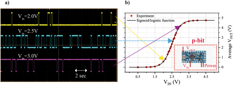
Figure 1.
p-bit emulated using Arduino microcontroller. Eq. (1) is emulated using the Arduino mini pro microcontroller as detailed in Algorithm 1. The microcontroller shown in the inset of (b) has dedicated analog input and digital output pins. The time evolution of the output voltages of p-bits is shown in (a) using a Tektronix DPO7104 oscilloscope. The p-bits produce more 1’s than 0’s as the input voltage is increased, demonstrating the tunable nature of the p-bit. Each of the red markers shown in (b) is a DC average measurement taken for a 100 second interval of the output voltage for a given input voltage. The average output voltages follows the sigmoidal function of Eq. (4).

