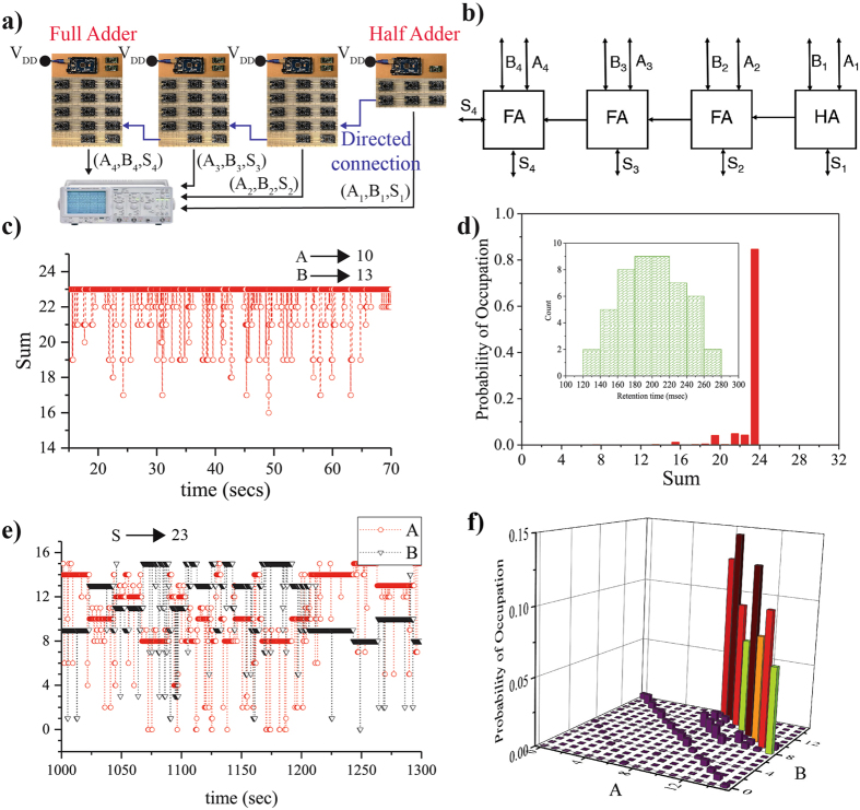
Figure 8.
4-bit Ripple Carry Adder (RCA). A 4-bit adder is implemented using 3 Full Adders and a Half Adder. A schematic and a block diagram are shown in (a) and (b). We assign each p-bit a separate retention time τ N, with a normal distribution shown in the inset. (c,d) When the inputs are clamped to A = 10 to B = 13 the output S is 23. (e,f) In the inverted mode the output S is clamped to 23, resulting in A and B going through all 8 combinations (that can be probed by 4-digit binary inputs A and B) of producing A + B = S = 23.

