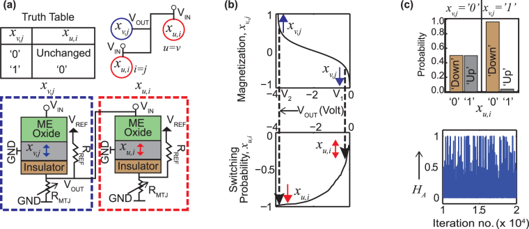
Figure 2.
(a) The truth table and the physical connection governing the interactions between spin units. Here x v,j acts as the input to x u,i and they lie either on the same row or same column. The MTJ in each device has been replaced by a variable resistance R MTJ. (b) Top panel: the variation of V OUT with x v,j, obtained from a behavioral model (V OUT = A tanh (Bx u,i)). Bottom panel: the switching probability of x u,i vs applied voltage, V IN (stochastic LLG simulation). The polarity of this voltage tends to switch x u,i from ‘1’ to ‘0’. (c) Top panel: a sample simulation of x u,i for two cases: x v,j = ‘0’ and ‘1’. Bottom panel: A plot of the Hamiltonian cycle, H A with time. H A is concentrated around 0, since the interactions are designed to make each product term x v,j x u,i = 0.

