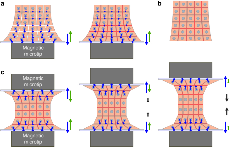
Fig. 7.
Schematic view of the forces involved within the EB in the magnetic stretcher. a Formation of the EB on the magnetic microtip located below a glass wall. Each cell is subjected to a magnetic force (blue arrow). The total resulting magnetic force (shown on the right-hand side, also in blue) is exactly balanced by the wall reaction force (green arrow). This pair of forces act like a “clamp” that holds mainly the “proximal” region of the sample, closest to the glass wall. After the magnetic contact, adhesion molecules (in red) develop the EB cohesion, without affecting forces. b The whole aggregate can then be used as a standalone EB. c When another magnetic microtip is approached with another glass wall, the upper cell layers are “clamped” against the upper wall in a similar way as in a. Varying the separation of both “clamps” makes it possible to adjust or cycle the (tensile) strain of the main part of the EB (represented here with a thickness of only two cells for simplicity, but actually corresponding to the major part of the entire EB)

