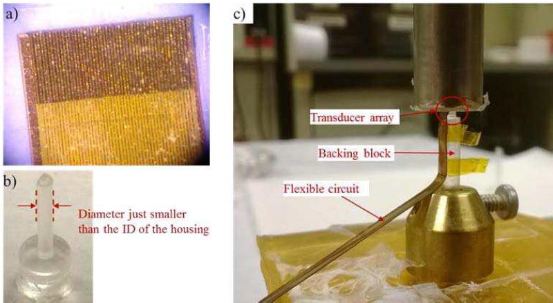
Fig. 5.
a) It shows the end of the flexible circuit bonded onto the composite. The traces on the circuit are aligned with the electrodes on the individual elements. b) The backing block made of Epotek 301 is shown. The diameter of the backing block is around 200 µm less than the inner diameter of the housing, so as to ease the positioning of the array at the center of the housing. c) The bonding process of the acoustic stack to the backing block is shown. The array sits at the top of the backing block (inside the red circle), and the flex circuit bends along the side of the backing block.

