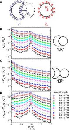
Fig. 2. Calculations of the electrostatically driven self-assembly of oppositely charged lock and key particles.

(A) Schematic representation of the oppositely charged lock and key particles used for the modeling of electrostatic interactions. (B) Minimum electrostatic energy in the lock-and-key (LK) configuration as a function of the size ratio, RK/RL, calculated for different ionic strengths using RL = 500 nm, ZL = −1000e, and ZK = +100e. (C) Same calculations as in (B) but in the configuration. (D) Energy difference between the and LK configurations at different ionic strengths (see text for more details).
