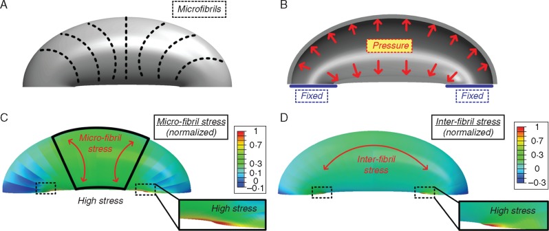
Fig. 9.
Stoma structural model used for the numerical simulations (A, B) and the resulting finite-elements numerical simulation (C, D). (a) Schematic description of the localized circumferential micro-fibril directionality in external view. (B) The simulations boundary conditions, fixed edge displacement and uniform internal pressure in cross-sectional view. (C) Normalized microfibril stress field; high microfibril stresses are obtained at the middle of the stoma and at the edges. Red arrows indicate the microfibril stress direction. (D) Inter-fibril stress field; high inter-fibril stresses are obtained at the stoma edges. Red arrow indicates the inter-fibril stress direction.

