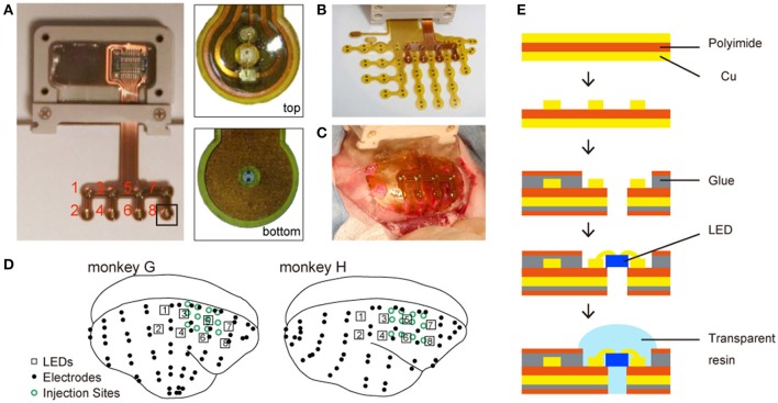
Figure 1.
Chronically implantable photostimulation device. (A) Left: an overview of the micro-LED array; right: magnified images from the experimenter's (top) and animal's (bottom) perspective. The red numbers indicate the number of each LED. (B) The LED and ECoG arrays. (C) An example of electrode implantation. (D) Locations of LEDs (numbered squares), electrodes (black dots), and virus injection sites (open green circles). (E) Fabrication of the LED array.

