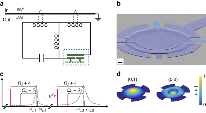
Fig. 2.

Implementation of a superconducting microwave circuit optomechanical device for nonreciprocity. a A superconducting circuit featuring two electromagnetic modes in the microwave domain is capacitively coupled to a mechanical element (a vacuum-gap capacitor, dashed rectangle) and inductively coupled to a microstrip feedline. The end of the feedline is grounded and the circuit is measured in reflection. b Scanning electron micrograph of the drum-head-type vacuum gap capacitor (dashed rectangle in a) with a gap distance below 50 nm, made from aluminium on a sapphire substrate. The scale bar indicates 2 μm. c Frequency domain schematic of the microwave pump setup to achieve nonreciprocal mode conversion. Microwave pumps (red bars) are placed at the lower motional sidebands—corresponding to the two mechanical modes—of both microwave resonances (dashed purple lines). The pumps are detuned from the exact sideband condition by ±δ = 2π ⋅ 18 kHz, creating two optomechanically induced transparency windows detuned by 2δ from the microwave resonance frequencies (denoted by ω c,1 and ω c,2, vertical dashed lines). The phase ϕ p of one the pumps is tuned. The propagation of an incoming signal (with frequency ω s,1 or ω s,2, solid grey bars) in the forward and backward direction depends on this phase and nonreciprocal microwave transmission can be achieved. d Finite-element simulation of the displacement of the fundamental (0, 1) and second order radially symmetric (0, 2) mechanical modes (with measured resonant frequencies Ω1/2π = 6.5 MHz and Ω2/2π = 10.9 MHz, respectively) which are exploited as intermediary dissipative modes to achieve nonreciprocal microwave conversion
