Figure 1.
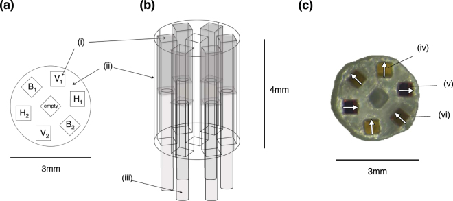
(a) Top view of 3-dimensional schematic of the printed component holder with six 500 μm × 500 μm micro-polariser pieces (i), oriented vertically (labelled V1 and V2), horizontally (H1 and H2), and at −45° (B1 and B2) in the holder (ii). (b) Side view of 3-dimensional printed component holder design, with optical fibres (iii) glued to the underside of each micro-polariser (i). (c) Top view of experimental 3D printed component holder with V, H and B micro-polarisers placed into position; the arrows represent their orientations. The photograph was taken through a vertical polariser sheet with a stereomicroscope; thus light reflected back off the white stereomicroscope stage through the horizontal polariser (v) is blocked, the light through the −45° polariser suffers a ~50% intensity loss (vi), and the vertical polariser intensity (iv) is largely unaffected. Other fibre geometries are possible to house the channels closer together, improving resolution, including arrangements that make use of the central channel. The depicted geometry was suitable for a proof-of-principle prototype demonstration.

