Figure 3.
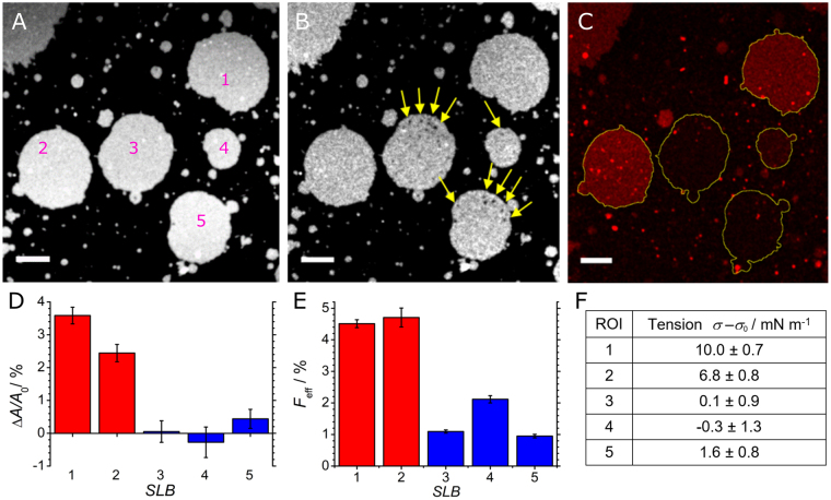
Membrane fusion of LUVs (red) to pre-stressed SLBs (white) monitored with confocal microscopy. (A) SLBs with an individually defined membrane area were created from spreading of GUVs containing the blue dye A390 on an expandable PDMS surface. (B) After stretching the patches, the membrane area of some of the patches increases. Frequently, holes in the bilayer may also appear (SLBs 3, 5) as highlighted by yellow arrows. (C) Fluorescence image of the same position showing emission of the red dye A594 after addition of LUVs. Fusion of LUVs was only observed with stretched planar membranes (SLBs 1, 2). Scale bar: 10 µm. (D) Relative membrane area change of the GUV patches after expansion of the PDMS sheet. SLBs 1, 2 show a substantial membrane area increase due to stretching of the PDMS sheet, while SLBs 3, 4, and 5 remain almost unstressed. (E) Fusion efficiency (Eq. 3) of LUVs at the different SLBs. SLBs 1, 2 show a significantly higher fusion efficiency compared to SLBs 3, 4, and 5. (F) Tension values obtained from Eq. (1) using the corresponding area dilatation.

