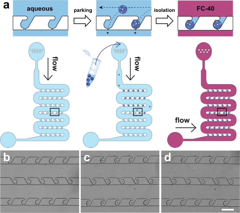
Figure 1. Microfluidic device and protocol for microparticle parking and isolation.
(a) Schematics of microparticle parking and isolation. The device is shown before parking, after parking, and after isolation with fluorinated oil (FC-40). The top row shows close-up images of the outlined area, and the bottom row shows the whole device during each of the three steps. (b-d) Bright field images of the microfluidic channel before parking (b), after parking (c), and after isolation (d). Only one particle occupies each trap, and trapped particles are isolated in individual homogeneous-sized droplets (volume < 500 pl; CV = 7.9%) with high yield. Yields of parking and isolation are 94.5 (± 5.3) and 96.4 (± 1.7) %, respectively. Scale bar is 300 µm.

