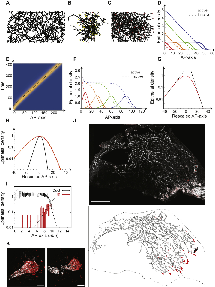
Figure S4.
Numerical Simulations of Branching and Annihilating Random Walks Are Captured by a Fisher-KPP Mean-Field Theory, Related to Figure 3
(A) Typical simulation output for branching and annihilating random walks with a regulation on the branching probability, and constant and uniform annihilation probability. Contrary to the default case, although the model succeeds in reproducing the constant ductal density along the AP-axis, numerous cross-overs can be seen in the simulation outputs.
(B) Typical simulation output for intrinsically balanced tip termination and branching, irrespective of local cues. This displays cross-overs and lack of space filling properties.
(C) Typical simulation output for classical branching and annihilating random walks where tip annihilation only occurs in contact to another active tip. Active tips are uniformly distributed along the gland, instead of sitting at the front of the invasion, and the ductal density displays a gradient, together with numerous cross-overs between ducts.
(D) The key aspects of (C) are well-captured by a mean field Fisher-KPP theory, for which we show a typical numerical integration output (rescaled branching rate = 1), for different time points (red, orange, green and blue represent successive times). The full lines represent the density of active tips, while the dashed lines represent the density of inactive particles, i.e., ducts.
(E) Kymograph of the numerical integration of Figure 3B, showing the propagation of a solitary pulse of active tips, traveling at constant density (rescaled branching rate = 0.1). The dashed line represents the analytical prediction for a speed of V = 21/2, which fits very well the numerical simulation.
(F) Stationary shape of the KPP pulse in the same numerical simulation as E/, with the x axis rescaled around 0 (red). The dashed black lines represent of the analytical prediction for the exponential decay length of the back and front of the front, fitting very well with the numerical simulations.
(G) Numerical integration of the Fisher-KPP equations, with the same parameters as Figure 3B, but making the approximation discussed in the STAR Methods that and . We observe very similar results, validating the approximation scheme, for different time points (red, orange, green and blue represent successive times). The full lines represent the density of active tips, while the dashed lines represent the density of inactive particles, i.e., ducts.
(H) Stationary shape of the KPP pulse, comparing three conditions: numerical integration of the full KPP equations as in (D) (full red line, = 0.1), approximation discussed in (F) (dashed orange line, = 0.1), and numerical integration of the full KPP equations for larger = 1, where the approximation becomes invalid (thin black line). For = 0.1, one notices that the approximation matches very well the integration of the full equation. Increasing = 1 produces sharper pulses as expected, but still leads to the same phenomenology discussed in the → 0 limit of a pulse which decays slower in the back that in the front.
(I) Experimental density of ducts (black) and proliferative tips (same as Figure 3D), overlaid with the fitted analytical prediction of an exponential decay at the front for both tips and ducts (dashed line). Importantly, the back of the pulse was well-fitted by the theoretical prediction of a slope √2 − 1 (less steep, dashed line).
(J) Reconstruction of a 5w third mammary gland following an Edu pulse, showing a similar result as Figure 3C, with a pulse of tips at the invasion front and large density fluctuations.
(K) Zoom on representative terminal end bud structures, i.e., active tips containing highly proliferative cells, from the boxes shown on I. Error bars represent mean and s.e.m.
Scale bars: 5 mm (I) and 100μ m (J). K14 in white, EdU in red.

