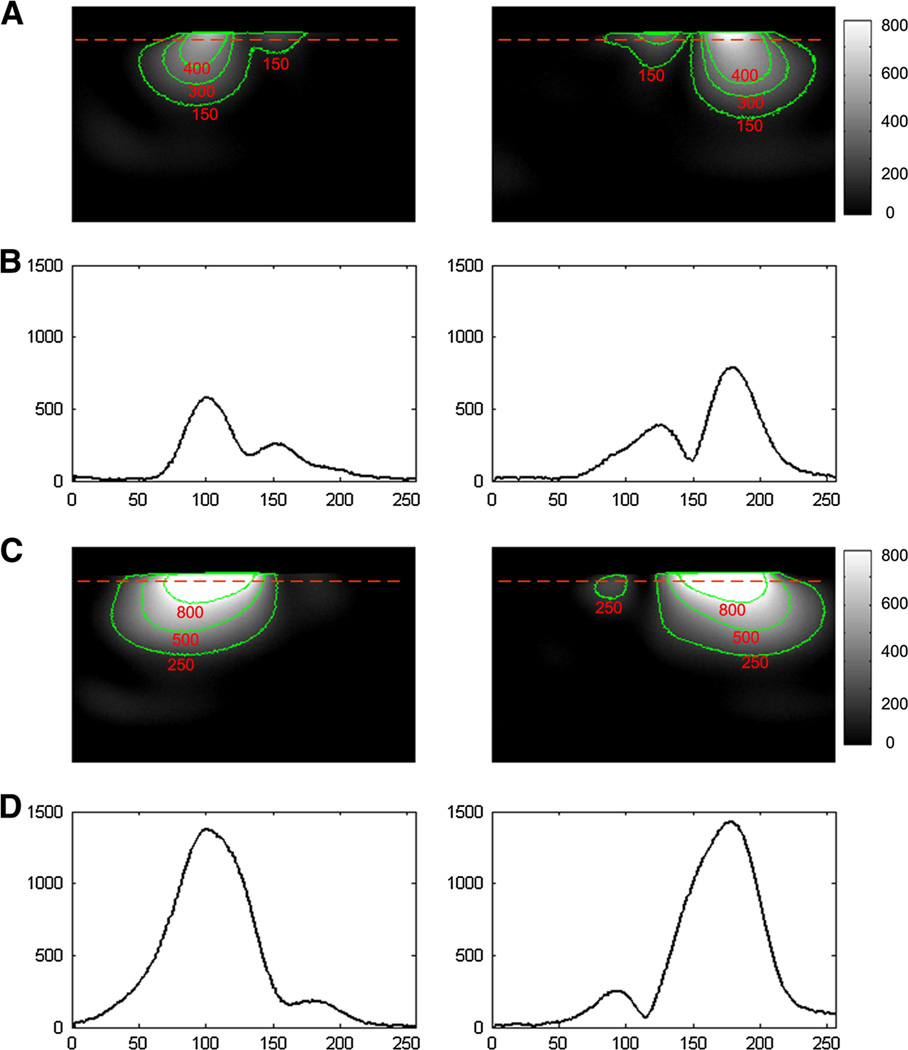
Fig. 4.
GRE images from each dipole element of the two-channel array without and with the magnetic wall decoupling. a Images from two coupled dipole elements. b Profile of the red dotted line of the images in a. The S21 between the two dipole antennas was about −3.6 dB, which indicates that about half of the signal power was coupled to the other element. The strong coupling between the two dipoles could also be observed from figures a and b. c Images from two MW decoupled dipole elements. d Profiles of the red dotted line of the images in c. Figures c and d show the strong decoupling performance between the two dipoles

