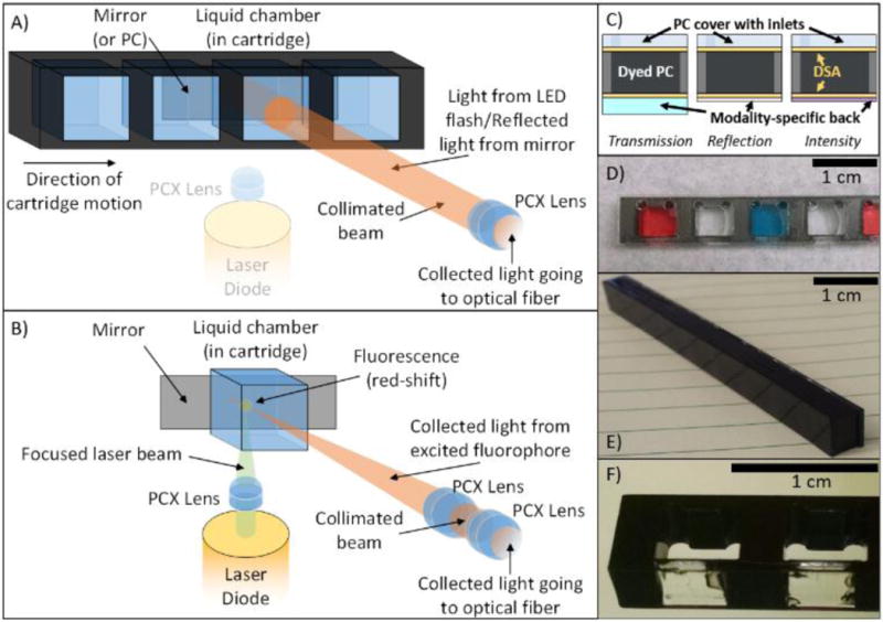
Figure 2.

Two principal light paths and cartridges for each of the three modalities. A) Reflection (PC-only) and Transmission (absorption or PC) optical pathway. Collimated light from the on-board smartphone flash is directed through the sample chamber. For reflection-based PC measurements, a back-coated cartridge prevents transmitted light from being collected. For transmission measurements, light is reflected by cradle mirror directed toward the collection fiber. B) Fluorescence/Luminescence Intensity optical pathway. A laser pointer diode is co-focused to a point near the back-side of the cartridge where the collection fiber is similarly focused via addition of a single plano-convex lens into the optical path via a SLA-printed slider actuated from outside the cradle. Additional cartridge wells/housing was removed for clarity in B). C) “Sandwich” style cartridge fabrication alternating plastic or glass substrates with double-sided-adhesive (DSA) showing how different backings facilitate different modalities. D) Transmission cartridge showing inlet/outlets and optically-isolated chambers. E) Dyed PC for label-free Reflection measurements. F) Close-up of Intensity cartridge demonstrating selectively-dyed cartridge body allowing for bottom-illumination with 532 nm laser diode.
