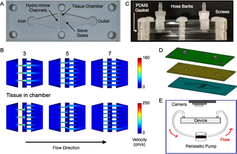
Figure 1.
Microfluidic digestion device design and operation. (A) Image of laser-etched acrylic sheet containing the chamber for loading tissue samples and fluidic channels including upstream (left) for hydro-mincing and downstream (right) sieves. (B) Finite-element fluid dynamics simulations showing velocity profiles in devices with different numbers of hydro-mince channels. Simulation results are shown at 1 mL/min flow rate with the chamber empty and partially blocked by a model tissue. Fewer hydro-mince channels will generate stronger fluidic jets to shear the tissue, but with less overall coverage. (C,D) Full digestion device shown in (C) side and (D) exploded views, with a PDMS gasket layer sandwiched between two acrylic sheets. Hose barbs were added to the top layer and nylon screws were used to hold the device together. (E) Experimental set-up for digestion experiments. Flow was driven by a peristaltic pump and tissue digestion was visually monitored with a camera mounted above the device.

