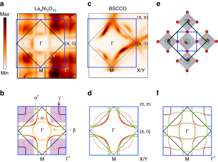
Fig. 1.
Fermi surface map of La4Ni3O10. a, b The unsymmetrized Fermi surface of La4Ni3O10 from ARPES measurement and schematic of the Fermi surface. c, d Fermi surface of optimally doped cuprate (Bi,Pb)2Sr2CaCu2O8+δ (BSCCO) and a schematic of its Fermi surface. The Fermi surface of La4Ni3O10 can be divided into three parts. The hole pocket centered at Γ′ is similar to the hole-doped cuprate Fermi surface (solid red–yellow curve) with the (π, π) back-folded band. This cuprate-like hole pocket corresponds to 17% of hole filling level. The other two parts are the extra electron (yellow circle in b) and hole (purple curve and hatched area) pocket around Γ and Γ′, respectively. e The real space unit cells of La4Ni3O10. The black box corresponds to the two Ni unit cells where the blue box corresponds to the origin Ni-O plaquette. f Drawing of the Fermi surface in the repeated zone representation where pockets are back folded into the small Brillouin zone. The light green curves in d and f represent the extra band expected from multilayer band splitting

