Figure 1.
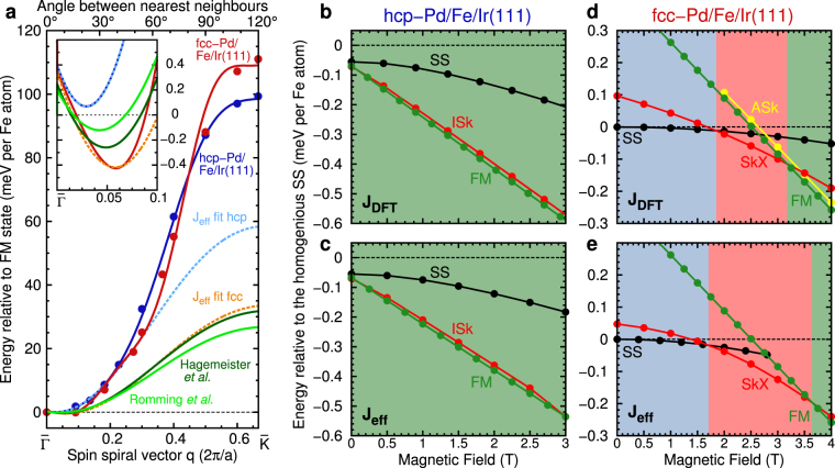
Energy dispersion of spin spirals and zero temperature phase diagrams of Pd/Fe/Ir(111). (a) Energy dispersion of homogeneous cycloidal right-rotating spin spirals for Pd/Fe/Ir(111) as a function of the spin spiral vector q along the -direction. The inset shows a zoom of the dispersion around the energy minima. Note that there is an offset for all curves at q = 0 due to the magnetocrystalline anisotropy which leads to an energy increase for all spin spiral states of K/2 with respect to the ferromagnetic state. The filled circles are total energies obtained from DFT for fcc (red) or hcp (blue) stacking of the Pd layer including spin-orbit coupling. The solid lines are fits to the Heisenberg model including the Dzyaloshinskii-Moriya interaction. The dashed lines are fits to the DFT energy dispersion close to the energy minima with an effective nearest-neighbor exchange interaction J eff and effective DMI for fcc (orange) and hcp (blue) stacking. For comparison, the energy dispersions for parameters given by Romming et al.24 (light green) and Hagemeister et al.26 (dark green) are shown. (b,c) Zero temperature phase diagram for hcp-Pd/Fe/Ir(111) obtained with the DFT (J DFT) and effective (J eff) parameters, respectively. The energies of the ferromagnetic (FM), isolated skyrmion (ISk) and relaxed spin spiral (SS) state are shown relative to the homogeneous spin spiral (dashed line). The green color indicates the regime of the FM ground state. (d,e) Zero temperature phase diagram for fcc-Pd/Fe/Ir(111) as in (b,c) including the skyrmion lattice (SkX) and the isolated antiskyrmion (ASk) state. Blue, red, and green color represents the regime of the SS, SkX, and FM ground state, respectively.

