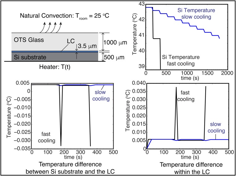
Fig. S6.
Heat transfer analysis. Schematic representation of the heating/cooling experimental setup (not to scale), including the boundary conditions for the heat transfer analysis. Transient finite-element simulations are used to generate a detailed picture of the heat transfer within the hybrid cell. The cell is heated/cooled from below with a known temperature; the cell also undergoes a slow cooling through the bottom OTS surface by natural convection. The temperature of the laboratory is controlled and constant at a value of 25 °C. The Si substrate temperature for the fast and slow cooling schemes is shown. From this boundary condition, the relevant values are the temperature difference between the Si substrate and the LC and the temperature difference within the LC. As shown in the results, these differences are of order 10−2 °C, which demonstrate that we do have a controlled-temperature setup for the LC.

