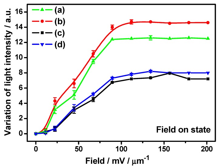
Figure 2.
The measured reorientation-induced light intensity variation of representative GP flakes according to Figure 1. The applied electric fields for Case I and Case II are 0, 22, 44, 67, 90, 100, 112, 134, 156, 180, and 200 mV/μm, respectively (Case I: flake area and aspect ratio in (a,b): 35 μm2 with an aspect ratio of 2:1 and 85 μm2 with an aspect ratio of 1:1; Case II: flake area and aspect ratio in (c,d): 37 μm2 with an aspect ratio of 2:1 and 90 μm2 with an aspect ratio of 1:1). The scattered points represent experimental data along with measurement error bars and the lines are guides for the eye. Error bars for respective data points are assigned considering standard deviations obtained in the repetitive observations.

