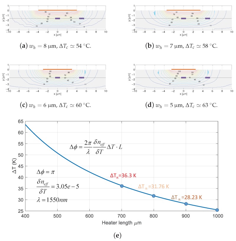
Figure 7.
Waveguide cross-section with heater on top, and adjacent waveguide at a distance of 5 m, with temperature gradient distribution overlaid. A dotted line is drawn from left to right crossing the core of the waveguides at half their height. Four different heater widths are shown (a–d), for the same heater length ( m). The contours are simulated for the same heater power consumption (same amount of heat generated), showing the temperature gradient is larger for narrow heaters. Panel (e) shows simulation results of temperature required for a phase shift vs. heater length. Abbreviations employed in the figure: heater width; , optical phase change; temperature change in the waveguide core; change in the effective index; temperature change causing a phase change of .

