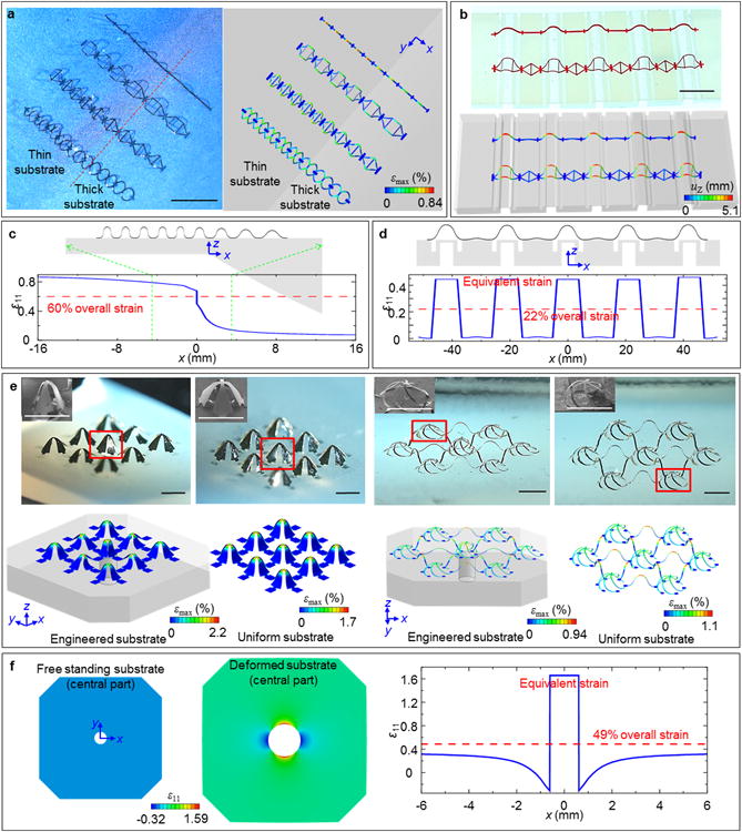
Figure 4. Various 3D structures enbabled by compressive buckling induced by spatially non-uniform strains in engineered substrates.

(a) Optical image of arrays of 3D ribbon structures made of silicon with a spatial gradient in key geometric features (left), and corresponding FEA results (right). (b) Optical image of related 3D structures made of thin films plastic with an abrupt change in key geometric features (left), and corresponding FEA results (right). (c) FEA results showing the side view of the structure shown in (a), and the magnitude of the x-direction normal strain for a 60% applied uniaxial strain. (d) FEA results showing the side view of the structure shown in (b), and the magnitude of x-direction normal strain for a 22% applied uniaxial strain. (e) Optical images of 3D structures made of bilayers of metal gold and photodefined patterns of epoxy (SU8) (top), and corresponding FEA results, including illustrations of the substrate geometries (bottom; only the central part of substrate is shown). The insets shows magnified SEM views of the regions identified with red boxes in each optical image. Experimental and FEA results of 3D structures formed using the same 2D precursors but with uniform substrates are on the right. (f) FEA results for the engineered substrates (only central part shown) before and after 49% biaxial stretching (left), and magnitude of normal strain ε11 for a 49% applied biaxial strain (right). The colors indicate the maximum principal strains in the structures for (a) and (e), and the magnitude of out-of-plane displacements for (b). Engineered substrates in (a), (b) and (e) are shown with 30% translucency. Scale bars in (a), 500 μm. Scale bars in (b), 1 cm. Scale bars in (e), 1000 μm.
