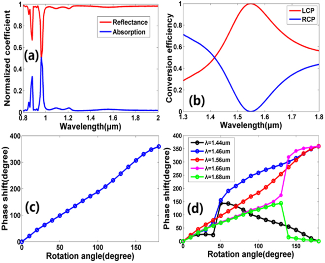
Figure 2.
(a) Simulated reflection and absorption coefficient of the unit cell as a function of the incident wavelength. (b) Simulated polarization conversion efficiency of the unit cell as a function of the incident wavelength. The red and blue lines represent the proportion of the LCP and RCP in the total reflected power, respectively. (c) Simulated phase shift for the nanoblock with rotation angle θ ranges from 0° to 180° with a step angle of 10° at wavelength λ = 1550 nm. (d) Simulated phase shift of the nanoblock with different rotation angle θ for various incident wavelengths. For these simulations, periodic boundary conditions are applied along the x and y axis and perfectly matched layers (PML) is applied along the z axis.

