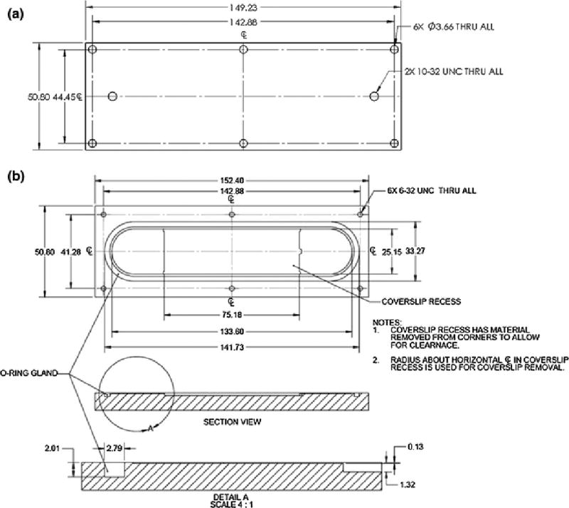
FIGURE 1.

Schematic diagram of the PPFC (a) top plate and (b) base. Base has a recess to accommodate a coverslip. The recess has material removed from corners to allow for clearance, and that the radius about the horizontal centerline is used for removal of the coverslip containing the EC monolayer.
