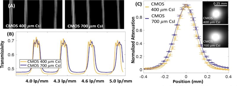
Figure 6.

(A) Details of a radiographic line pattern phantom imaged using two CMOS panels with different CsI thicknesses (nominal frequencies, from left to right: 4, 4.3, 4.6, 5 lp/mm). Average profiles though the line patterns are shown in (B). In (C), reconstructions of the Tungsten wire phantom are compared for the two CMOS panels. The thinner scintillator achieves 12% improvement in FWHM.
