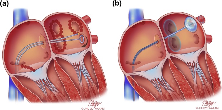
Fig. 9.
Schematic drawing showing catheter ablation of atrial fibrillation using either RF energy or cryoballoon AF ablation. a Shows a typical wide area lesion set created using RF energy. Ablation lesions are delivered in a figure of eight pattern around the left and right PV veins. Also shown is a linear cavotricuspid isthmus lesion created for ablation of typical atrial flutter in a patient with a prior history of typical atrial flutter or inducible isthmus-dependent typical atrial flutter at the time of ablation. A multielectrode circular mapping catheter is positioned in the left inferior PV. b Shows an ablation procedure using the cryoballoon system. Ablation lesions have been created surrounding the right PVs, and the cryoballoon ablation catheter is positioned in the left superior PV. A through the lumen multielectrode circular mapping catheter is positioned in the left superior PV. Illustration: Tim Phelps © 2017 Johns Hopkins University, AAM

