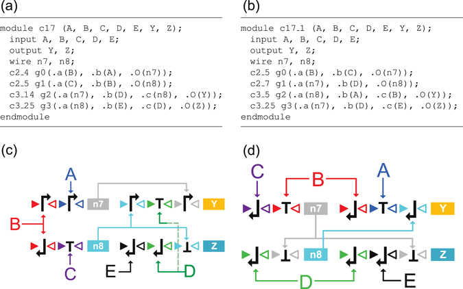
Figure 6.

Synthesis results of circuit c17 in Verilog descriptions and in DNA circuit implementations. (a) Tool ABC synthesized c17 circuit in Verilog description. (b) Manually designed c17 circuit in Verilog description. (c) DNA circuit implementation of the ABC synthesized circuit in (a). (d) DNA circuit implementation of the manually designed circuit in (b). In both (c) and (d), symbols A, B, C, D, and E indicate the recombinase inputs, the proteins encoded by the genes Y and Z are the outputs of the circuit, and the DNA gates encoding recombinases n 7 and n 8 and proteins Y and Z are the gates g0, g1, g2, and g3, respectively, in the modules c17 and c17_1.
