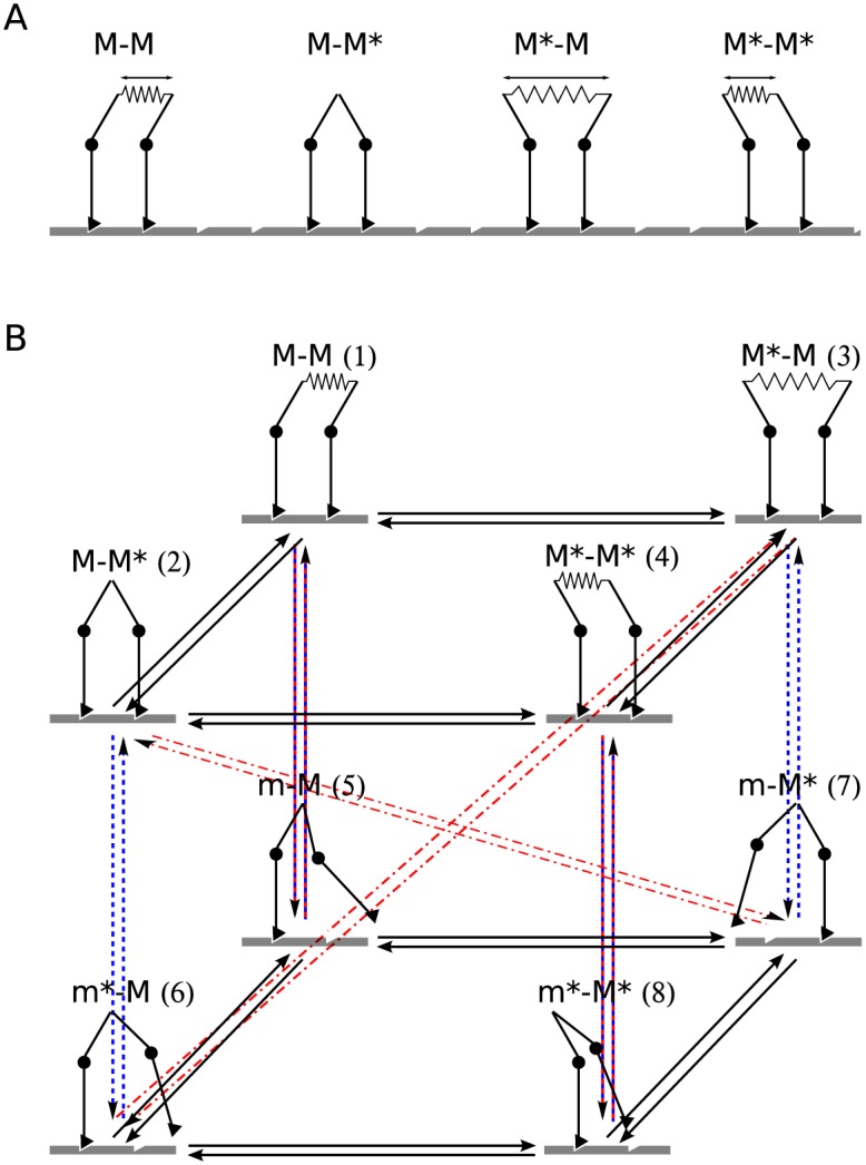
Fig 3. States in the dimeric motor.

(A) The bound states. The arrows show the extension of the elastic connector joining the two linkers. (B) Transitions between the states. Lower plane: Transitions between the states with one head unbound (states m, m*). Upper plane: Transitions between states with both heads bound. Arrows between the two planes show binding/unbinding of the lead (red) and the trail (blue) head.
