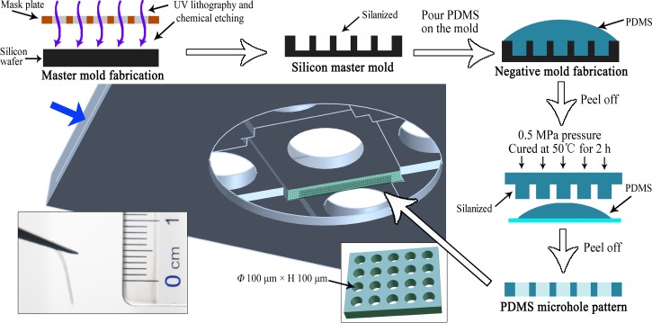
FIG. 2.
Schematic illustration of the protocol used to fabricate the PDMS microhole barrier. The microhole barrier was fabricated by soft lithography as shown on the top and right sides of the schematic. The middle schematic shows the location of one barrier, and the lower left photograph shows the fabricated PDMS microhole barrier. The blue arrow indicates the insertion position of the coverslip before each experiment.

