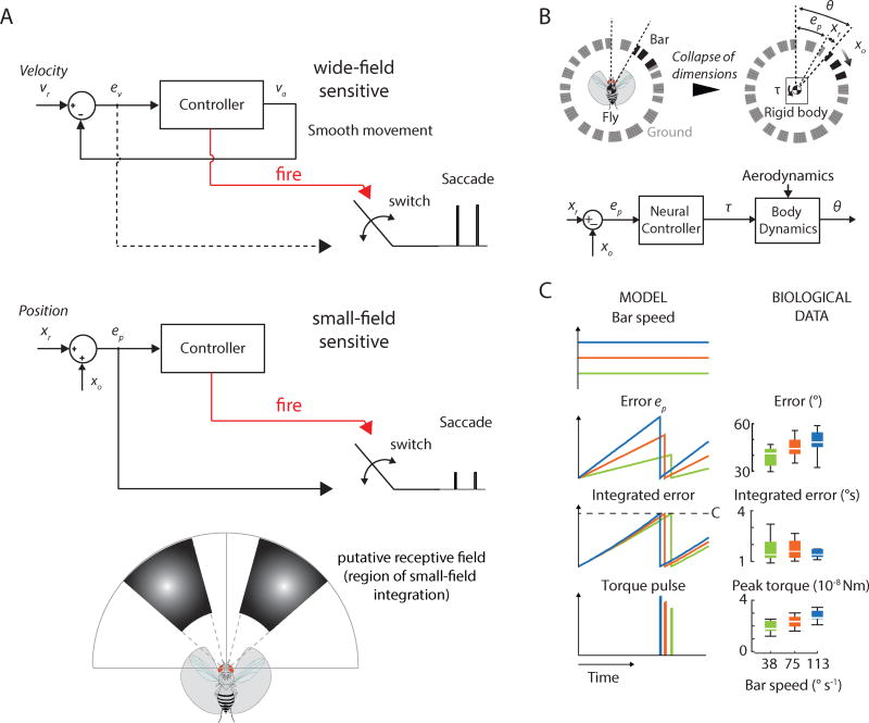
Figure 6. A switched, integrate-and-fire model simulates saccade control.
A) A parsimonious model of saccade control suggests parallel position and velocity controllers. Top: The velocity controller drives smooth movement and saccades whereas the position controller drives only saccades (bottom). Red lines: command (fire) signal when integrated error reaches a set threshold. The command signal triggers a change in switch state allowing the error to flow to generate appropriately scaled saccades. While not demonstrated explicitly, for the wide-field sensitive system we hypothesized that ev scales with motion speed to provide the appropriate tuning of saccades. vr: reference velocity; ev: retinal slip error; va: actual fly velocity; xr: reference position; ep: position error; xo: bar position. For the position controller, our data suggest a narrow, bilateral receptive field for integration of bar position. B) To determine whether a simple mechanism could simultaneously capture the constant-threshold saccade trigger and the tuning of control torque dependent on bar speed, we constructed a reduced-order, switched control model of bar fixation via a position controller. C) Error, integrated error and torque pulse amplitude generated for three simulated bar speeds (blue, green, red lines). The integrate-and-fire model fires when the integrated error reaches a constant threshold (C; Figure S6). The behavioral data is shown on the right for comparison. See also Figure S6.

